
Installation Instructions


- 6 -
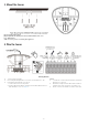
REMOTE LED ENABLE (LED INPUT)
(DT8360ACM only)
The LED input terminal allows the LED
to be remotely enabled. To use this
feature, the LED DIP switch (switch 2)
must be OFF, allowing the LED to
operate based on the voltage level
connected to the LED Input (see
Wiring Details).
Switch 2
LED Input
LED Operation
OFF High ( +12 V) Enabled
OFF Low (0 V) Disabled
ON
Low (0 V) or High (+12 V)
Enabled
RELAY OPERATION
SENSOR STATUS
Normal
Intrusion
Trouble
1
Mask
2
Alarm Relay
Closed
Open
Closed
Open
Trouble Relay
3
(DT8360ACM
only)
Closed Closed Open Open
1
For information on Trouble conditions, see the Troubleshooting section.
2
In a Mask condition, the Alarm and Trouble relays will activate
simultaneously, and remain open until the condition has been cleared.
3
In a Trouble condition, the Trouble relay will latch open until the Trouble
condition has been cleared.
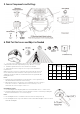
MASK CONDITION (DT8360ACM only)
Normal Anti-Mask Condition
The sensor uses Active Infrared (AIR) technology to detect
masking. The sensor signals a mask condition when a
variety of materials and reflective objects are placed within
50mm (2 inches) in front of the sensor. To avoid false
mask alarms, follow the mounting guidelines shown in
Step 1.
Clearing an Anti-Mask Condition
When most masking materials or objects are removed, the
anti-mask condition will be cleared after several seconds.
When the cause of the anti-mask condition is any type of
spray or paint coating applied to the window, the window
must be replaced before the anti-mask condition can be
cleared. After replacing the window, perform a walk-test on
the sensor.
TROUBLESHOOTING
TROUBLE*
NORMAL
Mask
1
Low
Voltage
2
Self-Test
Failure
3
Alarm Relay
Closed
Open
Closed
Closed
Trouble Relay
Closed
Open
Open
Open
Red LED
Off
Off
Off
Flashing
Yellow LED
Off
Flashing
Off
Off
*TROUBLE CONDITIONS:
1. Mask condition: Sensor IR window is blocked or
masked.
2. Low Voltage: The sensor is disabled. Note: If voltage
drops below 5V, both Alarm and Trouble relays open.
3. Self-Test Failure conditions:
• Microwave supervision failure: The sensor is
operating in PIR mode only.
• PIR self-test failure: The sensor is disabled.
• Temperature compensation failure: The
temperature compensation is disabled.
Depending on the Trouble condition, take the following
corrective actions:
• Verify the sensor is not blocked or masked.
• Verify the power supply is sufficient (at least 9V at the
sensor).
• Cycle power to the sensor.
• Walk test the sensor.
If the Trouble condition does not clear, replace the sensor.
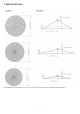
SPECIFICATIONS
Range: Ø 21m max.
Mounting Height: 2.4m – 8m
IP Rating: IP30
Power: 9.0 - 15 VDC; 10 mA typical, 20 mA max, 12 VDC;
AC Ripple: 3 V peak-to-peak at nominal 12 VDC
Alarm Relay: Energized Form A; 30 mA, 25 VDC, 22 Ohms
resistance max.
Alarm Relay Duration: 3 seconds
Trouble Relay: Energized Form B; (NC) 30 mA, 25 VDC;
22 Ohms resistance max.
Tampers: Cover & Wall; (NC with cover installed) Form A;
30 mA, 25 VDC; Magnetic field
Microwave Frequencies Range: 10.5 – 10.55GHz
RFI Immunity: 20V/m, 80MHz-1GHz
PIR White Light Immunity: 6,500 Lux typical
Fluorescent light filter: 50 Hz / 60 Hz
Operating Temperature: -10℃ - 55℃
Relative Humidity: 5 to 95%; non-condensing
Temperature Compensation: Advanced Dual Slope
Dimensions: 14.8 cm x 16.2 cm x 4.7 cm
Notes
• Install the devices and system in the isolated and
dedicated network system with physical security.
• Ensure only the authorized technician may access
and operate the device.
• Ensure to have regular system maintenance and
check the device functionalities work normally.
• Access
https://www.honeywell.com/contact-
us/vulnerability-reporting to report any vulnerability.