
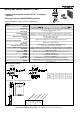
Safety Non Contact Switch Specifications


4
Safety Products for Machine Safeguarding - © 2002 - 2004 Honeywell International Inc. All rights reserved.
■■
■■
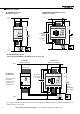
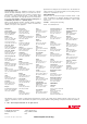
■ Connection diagram:
FF-SNC200R2 Control Unit FF-SNC400R2/FF-SNC400RE Control Unit
(Manual reset option) (Manual reset option)
GATE 2
A1 X1 BL DR 31 13 23
A2 X2 BL DR 32 14 24
GATE 1
GS2
GS1
K1 K2
K1
K2
Manual
Reset
24 V
(+)
24 V
(-)
K1
K2
F1
F2
POWER
IND 1
IND 2
RUN
24 Vdc
+
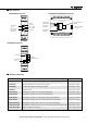
FF-SNC1EXT
Extension Module
FF-SNC400R2
Control Unit (24 Vdc)
24 Vdc
-
A1 BLDR
GATE 1
GS1
BLDR BLDR
GATE 2 GATE 3
GS2 GS3
A2 BLDR
GATE 4
GS4
BLDR BLDR
GATE 5
GS5
IND 1
IND 2
IND 3
IND 4
IND 5
POWER
RUN
POWER
GATE 4 GATE 3
1
2
3
4
GATE 4
GATE 3
GATE 2
DE-SELECT
A1
S13 S23
X1 BL DR BL DR 31 13 23
A2
S14 S24
X2 BL DR BL DR 32 14 24
GATE 2 GATE 1
GS3
GS1 GS2
K1 K2
K1
K2
K1
K2
F1
F2
Mechanical
safety switch
or E-Stop
FF-SNX1EXT+
FF-SNC400R2
8 Gate safety system
with optional
mechanical switch
or E-Stop input
and Manual Reset
Manual
Reset
(Momentary
Push-Button)
2
3
4
5
FF-SNC1EXT Extension Module
(can be used with FF-SNC400 or FF-SNC200 Series, 24 Vac/dc only)
RUN
POWER
GATE 4 GATE 3
GATE 4
GATE 3
GATE 2
DE-SELECT
A1
S13 S22
X1 BL DR BL DR 31 13
23
A2
S14 S24
X2 BL DR BL DR 32 14 24
GATE 2 GATE 1
GS3 GS4
GS1 GS2
K1 K2
Mechanical
Safety
Switches
or
Emergency
Stop
K1
K2
(+)
(-)
K1
K2
F1
F2
Manual
Reset
Up to 28 gates can be monitored using 6 extension modules with the FF-SNC400R2. The extension module can only be used
with the 24 Vac/dc control units.