
Installation Manual


69-2738EFS—03 4
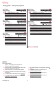
1H/1C Heat
Pump System
Rc Power [1]
R [R+Rc joined by jumper]
Y Compressor contactor
C 24VAC common
O/B Changeover valve [7]
G Fan relay
2H/1C Heat
Pump System
Rc Power [1]
R [R+Rc joined by jumper]
Y Compressor contactor
C 24VAC common
O/B Changeover valve [7]
G Fan relay
Aux/E Auxiliary/Emergency heat relay
2H/1C Heat
Pump System
Rc Power [1]
R [R+Rc joined by jumper]
Y Compressor contactor
C 24VAC common
O/B Changeover valve [7]
G Fan relay
Aux/E Auxiliary/Emergency heat relay
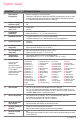
2H/2C Heat
Pump System
Rc Power [1]
R [R+Rc joined by jumper]
Y Compressor contactor (stage 1)
C 24 VAC common
O/B Changeover valve [7]
G Fan relay
Y2 Compressor contactor (stage 2)
3H/2C Heat
Pump System
Rc Power [1]
R [R+Rc joined by jumper]
Y Compressor contactor (stage 1)
C 24VAC common
O/B Changeover valve [7]
G Fan relay
Aux/E Auxiliary/Emergency heat relay
Y2 Compressor contactor (stage 2)
See [notes] below
MCR29448
RcY
GR
C
RcYGAux
E
LR
C
MCR29450
RcYGY2
LR
C
MCR29451
RcYGAux
E
LR
CY2
MCR29452
RcYGAux
E
LR
C
MCR29449A
NOTES
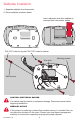
Wire specifications:
Use 18- to 22-gauge thermostat wire.
Shielded cable is not required.
[1] Power supply. Provide disconnect means and
overload protection as required.
[2] Remove jumper for 2-transformer systems.
[4] Common connection must come from cooling
transformer.
[5] In Installer Setup, set system type to Heat Only.
[6] In Installer Setup, set system type to
2Heat/2Cool Conventional.
[7] In Installer Setup, set changeover valve to O
or B.
[8] In Installer Setup, set system type to
2Heat/1Cool Heat Pump.
[9] In Installer Setup, set system type to
2Heat/2Cool Heat Pump.
[10] In Installer Setup, set system type to
3Heat/2Cool Heat Pump.
Wiring
Wiring guide — heat pump systems