
Install Instructions


H7625A, H7635A, H7626A, H7636A SERIES 2000 HUMIDITY/TEMPERATURE SENSORS
3 62-0327—03
WIRING
A 16 to 22 AWG shielded cable is recommended for all
transmitters. Twisted pair may be used for 2-wire current
output transmitters.
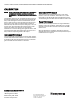
Refer to Figure 3 for wiring diagrams.
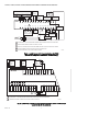
Fig. 3. Wiring Diagrams
CAUTION
It is recommended that you use an isolated UL-listed
class 2 transformer when powering the unit with 24
VAC. Failure to wire the devices with the correct
polarity when sharing transformers may result in
damage to any device powered by the shared
transformer.
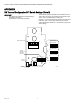
IMPORTANT
When using shielded cable, ground the shield only at
the controller end (see Fig. 4). Grounding both ends
can cause a ground loop.
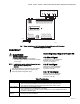
Fig. 4. Typical wiring diagram for transducer with two-wire mA
output with external DC power supply.
M31180A
TEMPERATURE SENSOR-
VOLTAGE OUTPUT SIGNAL
TEMPERATURE SENSOR+
0-10 OR 0-5 VDC OUTPUT SIGNAL
SUPPLY GROUND/SIGNAL COMMON
SUPPLY VOLTAGE
4-20mA VIN VOUT +TEMP-COM
TEMPERATURE SENSOR-
2 WIRE CURRENT OUTPUT SIGNAL
TEMPERATURE SENSOR+
SUPPLY VOLTAGE
4-20mA OUTPUT
4-20mA OUTPUT
4-20mA VIN VOUT +TEMP-COM
TEMPERATURE SENSOR-
3 WIRE CURRENT OUTPUT SIGNAL
TEMPERATURE SENSOR+
SUPPLY GROUND/SIGNAL COMMON
SUPPLY VOLTAGE
4-20mA VIN VOUT +TEMP-COM
TB1
TB1
TB1
mA OUTPUT
TRANSDUCER
ONLY
18 TO 36 Vdc
POWER SUPPLY
CONTROLLER, METER
OR RECORDER
INPUT SIGNAL
COMMON
Vin +
+
4-20mA –
–
M22528A
GROUND