
Install Instructions

H7625A, H7635A, H7626A, H7636A SERIES 2000 HUMIDITY/TEMPERATURE SENSORS
62-0327—03 6
APPENDIX
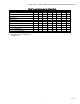
RH Test and Configuration DIP Switch Settings (Table 3)
IMPORTANT
• Only adjust these switches for troubleshooting or
recalibrating the sensor.
(Adjustment is not normally necessary.)
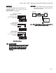
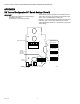
Test mode will make the transmitter output a fixed 0%, 50%, or
100% value. The sensor will not affect the transmitter output.
This is used for troubleshooting or testing only.
Switches 1, 2, and 3 are used for test mode. The output will be
a fixed 0%, 50%, or 100% signal that corresponds to the
output selected with switches 6, 7, and 8. Refer to Figure 4 for
switch settings.
1
ON
2345678
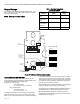
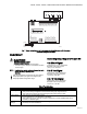
WIRE CONNECTIONS
M33163
SW1
TB1
OUTPUT,
CALIBRATION
AND TEST
SWITCHES
4-20mA VIN VOUT +TEMP-COM
P1P2
ZEROSPAN
1
ON
2345678
TEST SELECTION
SWITCHES (SW1)
0% RH OUTPUT
ON
OFF
1
ON
2345678
ON
50% RH OUTPUT
OFF
1
ON
2345678
ON
100% RH OUTPUT
OFF
SW1
SW1
SW1
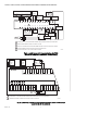
HUMIDITY
SENSOR
TEMPERATURE
SENSOR
S1
S3
S2