
Install Instructions

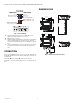
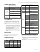
Table Of Contents

H7625, H7726, H7735, H7736 HUMIDITY/TEMPERATURE SENSORS
31-00444M—01 2
Fig. 2. Sensor Wiring.
4. Set DIP switch positions to accommodate your
application. DIP switch 2 is not used.
5. Apply power to sensor.
6. Tighten cable gland firmly around wires. If installing
with a conduit adapter, seal wire entry to prevent
conduit air from affecting sensor readings or opera-
tion.
7. Close lid and tighten screw. Cover must be securely
installed to prevent moisture from entering enclo-
sure.
OPERATION
Press center MENU button once to access the %RH offset.
A red LED will blink to indicate the %RH offset setting can
be adjusted.
The down W arrow and up V arrow can be used to
decrease or increase offset values in 0.1 increments up to
±5%.
DIMENSIONS
Fig. 3. Dimensions in inches (mm).
PWR
I
V
GND
T-I
T-V
TRNT
4.4 (113)
3.7 (94)
4.0 (101)
4.7 (119)
5.4 (137)
8.9 (226)
2.1 (53)
4.4 (113)
3.7 (94)
4.0 (101)
4.7 (119)
5.4 (137)
1.9 (48)
7.5 (190)
2.1 (53)