
Install Instructions
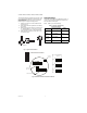
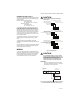
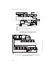
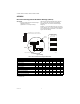
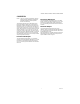
Table Of Contents

H7625B, H7626B, H7635B,C H7636B, H7655B, H7656B
3 62-0330—01
REVERSE ACTING OUTPUT
The output can be changed to reverse acting mode. The
output range stays the same but the corresponding RH
value is opposite.
Example: Direct Acting (DA) (Default)
0-10V output mode
0V = 0% RH and 10V = 100% RH
Reverse Acting (RA)
0-10V output mode,
0V = 100% and 10V = 0%
To change the transmitter to reverse acting or back to
direct acting, set switch 4 ON to put the unit in setup
mode. After switch 4 is on, switch 2 will put the unit in
direct/reverse acting mode. When switch 2 is set to ON,
the output can be used to show if the unit is in direct or
reverse acting mode. For direct acting the output will be
1V for 0-5V, 2V for 0-10V, and 7.2mA for 4-20mA. For
reverse acting the output will be 4V for 0-5V, 8V for 0-10V,
and 16.8mA for 4-20mA.
With switches 2 and 4 ON, each time switch 5 is set to
ON the output will change to reverse acting or direct
acting.
To reset the unit to the default setting, toggle both
switches 5 and 6 ON then OFF while both switches 2 and
4 are ON.
When all calibration is completed, remember to place the
switches back into the positions that correspond to the
output needed as shown in Figure 3.
WIRING
A 16 to 22 AWG shielded cable is recommended for all
transmitters. Twisted pair may be used for 2-wire current
output transmitters. the connections to the temperature
sensor should be made with wire nuts or crimp-style
connectors.Refer to Figure 3 for wiring diagrams.
CAUTION
Never connect or disconnect wiring with
power applied.
Fig. 3. Wiring Diagrams
CAUTION
It is recommended that you use an isolated
UL-listed class 2 transformer when powering
the unit with 24 VAC. Failure to wire the
devices with the correct polarity when sharing
transformers may result in damage to any
device powered by the shared transformer.
IMPORTANT
When using shielded cable, ground the shield
only at the controller end (see Fig. 4). Grounding
both ends can cause a ground loop.
Fig. 4. Typical wiring diagram for transducer with two-
wire mA output with external DC power supply.
M31321
TEMPERATURE SENSOR-
VOLTAGE OUTPUT SIGNAL
TEMPERATURE SENSOR+
0-10 OR 0-5 VDC OUTPUT SIGNAL
SUPPLY GROUND/SIGNAL COMMON
SUPPLY VOLTAGE
4-20mA VIN VOUTCOM
CONNECT TO THE 2
22 AWG 24” FLYING LEADS
CONNECT TO THE 2
22 AWG 24” FLYING LEADS
CONNECT TO THE 2
22 AWG 24” FLYING LEADS
2 WIRE CURRENT OUTPUT SIGNAL
TEMPERATURE SENSOR+
SUPPLY VOLTAGE
4-20mA OUTPUT
4-20mA OUTPUT
4-20mA VIN VOUTCOM
TEMPERATURE SENSOR-
TEMPERATURE SENSOR-
3 WIRE CURRENT OUTPUT SIGNAL
TEMPERATURE SENSOR+
SUPPLY GROUND/SIGNAL COMMON
SUPPLY VOLTAGE
4-20mA VIN VOUTCOM
TB1
TB1
TB1
mA OUTPUT
TRANSDUCER
ONLY
18 TO 36 Vdc
POWER SUPPLY
CONTROLLER, METER
OR RECORDER
INPUT SIGNAL
COMMON
Vin +
+
4-20mA –
–
M22528A
GROUND