
Install Instructions
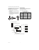
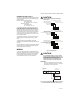
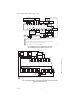
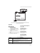
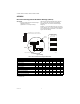
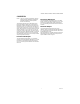
Table Of Contents

H7625B, H7626B, H7635B,C H7636B, H7655B, H7656B
62-0330—01 6
APPENDIX
RH Test and Configuration DIP Switch Settings (Table 3)
IMPORTANT
• Only adjust these switches for troubleshooting or
recalibrating the sensor.
(Adjustment is not normally necessary.)
Test mode will make the transmitter output a fixed 0%,
50%, or 100% value. The sensor will not affect the
transmitter output. This is used for troubleshooting or
testing only.
Switches 1, 2, and 3 are used for test mode. The output
will be a fixed 0%, 50%, or 100% signal that corresponds
to the output selected with switches 6, 7, and 8. Refer to
Figure 4 for switch settings.
Fig. 8. Settings
Table 3. Test and Calibration Settings (8-Switch Block).
* = Switch setting does not affect output
** = This switch needs to be activated first
— = Indicates OFF
Setting 12345678
4-20mA Output ————————
0-5 VDC Output —————OnOn—
0-10 VDC Output ——————OnOn
0% RH Output On———————
50% RH Output —On——————
100% RH Output ——On—————
Increment RH Output ———On**On———
Decrement RH Output ———On**—On——
Reset to Original Calibration ———On**OnOn——
Reverse or Direct Acting — On — On** On — — —
Reverse or Direct Acting Reset — On — On** On On — —
1
ON
2345678
WIRE CONNECTIONS
FACTORY
USE ONLY
PUSH TAB IN AND PULL ON THE SENSOR
CABLE TO REMOVE FROM J13 CONNECTOR
RED
FACTORY
USE ONLY
M31322
SW1
TB1
J2
J13
J14
4-20mA VIN VOUTCOM
P1P2
ZEROSPAN
GREEN
BLUE
1
ON
2345678
TEST SELECTION
SWITCHES (SW1)
0% RH OUTPUT
ON
OFF
1
ON
2345678
ON
50% RH OUTPUT
OFF
1
ON
2345678
ON
100% RH OUTPUT
OFF
SW1
SW1
SW1