HC900 Hybrid Controller Installation and User Guide Industrial Measurement and Control Doc. No.
Notices and Trademarks Copyright 2003 by Honeywell Revision 5 Sept. 2003 Warranty/Remedy Honeywell warrants goods of its manufacture as being free of defective materials and faulty workmanship. Contact your local sales office for warranty information. If warranted goods are returned to Honeywell during the period of coverage, Honeywell will repair or replace without charge those items it finds defective.
About This Document Abstract This document provides descriptions and procedures for the installation, operation and maintenance of the HC900 Hybrid Controller hardware. References The following list identifies all documents that may be sources of reference for material discussed in this publication.
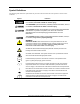
Symbol Definitions The following table lists those symbols that may be used in this document and on the product to denote certain conditions. Symbol Definition This DANGER symbol indicates an imminently hazardous situation, which, if not avoided, will result in death or serious injury. This WARNING symbol indicates a potentially hazardous situation, which, if not avoided, could result in death or serious injury. This CAUTION symbol may be present on Control Product instrumentation and literature.
Contents Introduction ............................................................................................. 1 Purpose ........................................................................................................................1 Functional Description ..................................................................................................2 Functional Description ..................................................................................................2 Feature Summary...
Communications Installation ................................................................. 85 Overview.....................................................................................................................85 Connecting the HC900 Controller to a PC with the Hybrid Control Designer Software88 RS-485 Link to Operator Interface ...........................................................................100 Connecting the HC900 Controller to Modbus device(s).......................................
DC Input Module.......................................................................................................165 AC Input Module.......................................................................................................166 Features Common to all Output Modules.................................................................166 DC Output Module....................................................................................................167 AC Output Module .........................
Tables Table 1 – Descriptions of Major Components (Figure 3)..............................................................................................7 Table 2 Simultaneous serial port configurations .........................................................................................................19 Table 3 - Open System Interconnection Model ...........................................................................................................25 Table 4 - Networking Device Types.............
Figures Figure 1 – Small HC900 Controller Configuration ......................................................................................................2 Figure 2 – Expanded HC900 Controller Configuration (C50 CPU only)......................................................................2 Figure 3 - Configuration with Multiple Controllers ......................................................................................................6 Figure 4 - Controller Rack Components.......................
Figure 54 - Pathways for Upload/Download Transactions........................................................................................114 Figure 55 - LED Indicators........................................................................................................................................118 Figure 56 - Terminal Board Connections for AI Calibration.....................................................................................
Introduction Purpose This publication describes the Honeywell HC900 Hybrid Controller, and facilitates its installation, operation, and maintenance. This publication includes the following sections. Section Title Section Content Introduction Describes the content and purpose of this manual relative to other manuals for the HC900 Hybrid Controller. System Overview Functional features and physical characteristics of the system and of each major component of the HC900 Hybrid Controller.
Introduction - Functional Description Functional Description The Honeywell HC900 Hybrid Controller is an integrated loop and logic controller that is designed specifically for small- and medium-scale unit operations It comprises a set of hardware and software modules that can be assembled to satisfy any of a broad range of process control applications.
Introduction - Feature Summary The HC900 Controller design enables users and OEMs who are adept in system integration to assemble a system that fits a broad range of requirements. Any configuration can be readily modified or expanded as requirements dictate. In initial configuration and in subsequent modifications, the HC900 Controller affords an optimum balance of performance and economy.
Introduction - Feature Summary Control Functions • • Comprehensive set of Function Blocks; includes: − PID: Model C50 - up to 32 loops Model C30 – up to 8 loops − Setpoint Programmers: up to 8; SP Profiles: pool of 99, with up to 50 Segments/Profile; SP Schedulers: 1 or 2; Setpoint Schedules: up to 20, with up to 50 Segments/Schedule − Sequencers: up to 4; Sequences: up to 20; Steps per Sequence: up to 64 − Recipes: up to 50; up to 50 parameters per recipe; − Logic, Fast Logic − Counters/Timer
Components and Architecture Overview This section provides a description of each of the major components that can be included in an HC900 Controller physical configuration, and indicates some of the methods by which they can be combined. Components The Honeywell HC900 Hybrid Controller includes a set of hardware modules that can be combined and configured as required for a wide range of small to medium process control applications. Some of the modules are required in all configurations.
Components and Architecture - Components Figure 3 - Configuration with Multiple Controllers 6 HC900 Hybrid Controller Installation and User Guide Revision 5 9/03
Components and Architecture - Components Table 1 – Descriptions of Major Components (Figure 3) Key No. Component Name Description 1 Controller (Local) Rack Includes: Rack, Power Supply, Controller Module, and I/O modules Honeywell 2 I/O Expansion Rack (C50 CPU only) (Optional) Includes: Rack, Power Supply, Scanner Module, and I/O modules Honeywell 3 Operator Interface (Optional) link to RS-485 port on a Controller Module; provides operating and utilities displays.
Components and Architecture - Hardware Components Hardware Components This section contains general descriptions of each of the major components of the HC900 system. For environmental specifications, refer to the section on Pre-Installation Planning. HC900 Controller Rack An HC900 Controller ("local rack") is shown in Figure 4. As indicated in this figure, the Controller Rack includes: 1. a Rack, available in 4- 8-, or 12-slot versions 2. a Power Supply 3. a Controller Module 4.
Components and Architecture - Hardware Components Rack Options Racks are available in 4-slot, 8-slot, and 12-Slot versions. Racks are interchangeable between the Controller rack and an IO expansion rack (C50 CPU only), and all three versions shown in Figure 6 are available for either purpose. Figure 6 - Rack Options Power Supply The P01 Power Supply, shown in Figure 7, provides 5 Vdc and 24 Vdc to the backplane connectors in the local and remote racks.
Components and Architecture - Hardware Components Controller Module The Controller Module is shown in Figure 8 with the hinged protective door open. Features at the front of the Controller Module include: 1 - a lithium battery (beneath cover), which is readily accessible for field replacement.
Components and Architecture - Hardware Components Input/Output Modules Eight input/output types are available: • • Analog − Universal Analog Input, 8-point − Analog Output, 4-point Digital − 120/240 Vac input, 16-point − 24 Vdc input, 16-point − Contact input, 16-point − 120/240 Vac output, 8-point − 24 Vdc output, 16-point − Relay output, 8-point Figure 10 - I/O Module Terminal Blocks Each I/O module includes a status indicator for the module.
Components and Architecture - Hardware Components Personal Computer A Personal Computer is required for creating the control and data acquisition strategy (configuration file) that runs in the controller, using the Hybrid Control Designer configuration software. The PC can also be used to download/upload configuration files to/from the controller, and can be used to download program updates to firmware in the Controller Module and/or Scanner Modules.
Components and Architecture - Ethernet Devices/Considerations Ethernet Devices/Considerations Ethernet device requirements vary with specific applications. Regarding intended use, however, they fall into two categories: • Components of the Ethernet Open Connectivity Network, which links an HC900 Hybrid Controller to Peers, to HMI Supervisory Stations, and to other Ethernet 10Base-T devices that support TCP/IP.
Components and Architecture - Ethernet Devices/Considerations The Ethernet Hubs used in the I/O expansion network (C50 CPU only)are available from Honeywell. I/O implementation requirements include: • Constructing a configuration file, and loading it into the Controller Module. This file includes I/O numbering assignments for each I/O Function Block regarding Rack Number, Module Number ("slot" number, or position in the rack, starting from the left), and Channel Number.
Components and Architecture - Ethernet Devices/Considerations Implementing peer-to-peer communications involves: • Interconnecting controllers with Ethernet media and networking devices (cables, hubs, switches, etc) • Configuration (via Hybrid Control Designer): − Controller configuration, which includes entry of an IP address (and if applicable, a Subnet Mask) and a Controller Name for each controller.
Components and Architecture - Ethernet Devices/Considerations Note: PDE communications, discussed previously, do not use the PC host connection sockets. PDE communications are separate from (and are transmitted concurrent with) PC host-to-controller communications. The PC host can include software that closely relates to and supports controller functioning and can also include other software that is related remotely or not at all.
Components and Architecture - Ethernet Devices/Considerations HMI software available for use with the HC900 Controller includes, but is not necessarily limited to the packages whose descriptions follow. • • available from Honeywell − PlantScape SCADA or Vista Software, which operates under Windows 2000 operating software, provides PC-based supervisory control and data acquisition.
Components and Architecture - Ethernet Devices/Considerations E-Mail Communications The HC900 Controller includes e-mail software that enables communication of Alarms and Events to up to three Internet addresses.
Components and Architecture - Serial Ports (RS232 and RS485) Serial Ports (RS232 and RS485) Overview • Ports configurable as ELN, Modbus RTU or Modbus TCP protocol. • Controller can act as Modbus master or slave through either port. • Controller can be master to slaves such as • − Honeywell Operator Interface (1040, 559). Must be on 485 port. Will not work on 232 port with 232/485 converter.
Components and Architecture - Serial Ports (RS232 and RS485) 1 ELN and ELN 2 Modbus Slave and ELN 3rd Party HMI Modbus Master ELN Protocol RS-232 RS-232 RS 485 2000 Ft ELN protocol 2000 Ft RS 485 3 ELN and Modbus Slave Modbus Slave Protocol ELN protocol Modbus Master and ELN 4 Modbus Slaves Honeywell A IL M % RS232 to RS485 Converter ELN Protocol RS232.
Components and Architecture - Serial Ports (RS232 and RS485) 7 Modbus Slave and Modbus Master Modbus Master and Modbus Slave 3rd Party HMI Modbus Master RS 485 % Honeywell A IL M Honeywell A IL M 2000 Ft RS 485 Modbus Master Protocol % % Modbus Master Protocol RS-232 2000 Ft Honeywell A IL M RS232 to RS485 Converter Modbus Slave Protocol RS-232 8 Modbus Slaves Honeywell A IL M Modbus Slave Protocol % 3rd Party HMI Modbus Master Modbus Slaves ELN and Modbus Master 10 9 Modbus Slav
Components and Architecture - Networking Basics Reference See also Refer to Communications Installation on page 85 for details on communications. Networking Basics Reference The following information provides a basic reference for identifying and applying networking concepts, components, and methods.
Components and Architecture - Networking Basics Reference operates in Layer 3, IP operates at Layer 2, and Ethernet itself includes protocols that operate at Layers 1 and 2.
Components and Architecture - Networking Basics Reference Characteristics of Networking Devices Table 2 summarizes the characteristics of a set of "generic" networking devices. The information in this table is intended to provide a basic overview of each type of device. Many devices that are currently available are hybrids that combine features of more than one device type included in the table. Glossary of Networking Terms A glossary of networking terms is given in Table 5.
Components and Architecture - Networking Basics Reference Table 3 - Open System Interconnection Model Layer Function Number .. Name 7. Application Identifies communications partners, quality of service, authentication and privacy, and syntax constraints Components reside in: Protocols PC Networking Software (e.g., Windows Client, Novell Client32) FTP (examples) SMTP Network components affected (examples) Networking software packages in PC hosts Modbus drivers 6.
Components and Architecture - Networking Basics Reference Table 4 - Networking Device Types Network Device Hub Description Notes A Hub is so called because a diagram of its connections resembles a hub of a spoked wheel. Characteristics: Echoes a message on any port to all other ports; constitutes a collision domain for all connected devices. Isolates the device(s) on a "bad" port.
Components and Architecture - Networking Basics Reference Table 5- Glossary of Networking Terms Name/Acronym Name/Definition 10Base-Tx Specification for 10mbps carried over twisted-pair cable. ARP Address Resolution Protocol AUI Bit bps Bridge Attachment Unit Interface A unit of binary data. Bits Per Second A networking device that connects two LANs and forwards or filters data packets between them, based on their destination addresses.
Components and Architecture - Networking Basics Reference Name/Acronym Collision Collision Detection Crosstalk Cross-over Cable CSMA/CD CSU/DSU Cut-Through Data Link Data Link Layer Datagram DCE DHCP Name/Definition Comments Simultaneous transmission of two nodes on the same channel. An indication to the Data Link Layer that node contention (simultaneous transmission) is present at the Physical Layer.
Components and Architecture - Networking Basics Reference Name/Acronym Domain Name DS1, DS3 DTE Name/Definition A text name, appended to the Host name. Dedicated leased telephone lines Data Terminal Equipment Ethernet IEEE networking standard 802.3, which defines configuration rules for an Ethernet network FTP File Transfer Protocol Filtering Selection process used by a Switch or a Bridge to forward a message or block its passage.
Components and Architecture - Networking Basics Reference Name/Acronym Name/Definition IP Address Internet Protocol Address ISDN Integrated Services Digital Network Corrupted and/or incessant data transmitted onto a network. Kilobits per second A program used widely for file transfer and terminal emulation. Local Area Network Jabber Kbps Kermit LAN Latency MAC Delay in transmission caused by a Switch or Bridge in forwarding a message. One of the seven layers in the OSI model.
Components and Architecture - Networking Basics Reference Name/Acronym Name/Definition Comments Modbus TCP/IP Variant of Modbus protocol Modem Modulator-Demodulator; a device for translating data in differing media and/or format. Transmission of a message with multiple destinations.
Components and Architecture - Networking Basics Reference Name/Acronym Node OPC Name/Definition Comments Any intelligent device that includes a hardware address that can be recognized by other network devices. Object Linking and Embedding (OLE) for Process Control The “node” terminology is sometimes limited to computing devices such as PC hosts, but can also include networking devices such as Switches and Routers.
Components and Architecture - Networking Basics Reference Name/Acronym RJ-45 Router Shared Ethernet SMTP SNMP SQE Name/Definition Style of connector at end of Ethernet twisted-pair cable A device that is capable of filtering messages based on IP addresses. Configuration that binds several network segments in a single collision domain. Simple Mail Transport Protocol Simple Network Management Protocol Signal Quality test Straight Cable Ethernet cable that enables connection of DCE to DTE equipment.
Components and Architecture - Networking Basics Reference Name/Acronym Name/Definition Comments Telnet Application that provides a terminal interface between hosts using TCP/IP. Telnet defines a protocol that allows a remote terminal session to be established with an Internet host, so that a remote user has can use the remote host as though he was sitting at a terminal connected directly to the Host. Throughput Data volume transmitted per unit of time.
Pre-Installation Planning - Networking Basics Reference Revision 5 9/03 HC900 Hybrid Controller Installation and User Guide 35
Pre-Installation Planning - Overview Pre-Installation Planning Overview Methodical pre-planning of an installation will preclude false starts and errors that can cause costly hardware re-configuration and/or poor system performance. Some considerations in pre-installation planning should include: 36 • Power Supply Budgeting • Environmental conditions such as temperature, humidity, and other characteristics of the physical plant site.
Pre-Installation Planning - Power Supply Selection Power Supply Selection To determine which power supply to use, calculate power requirements below. ATTENTION Using inadequate power supply will cause the controller to cycle power on and off. Enter quantity of each module type in column A and calculate the 5V and 24V maximum current in columns D and E. Sum the maximum current for all module types and determine if the 900P02 power supply is appropriate.
Pre-Installation Planning - Environment Environment Environmental Operating Limits The environmental conditions required for operating the HC900 Hybrid Controller are listed Table 6.
Pre-Installation Planning - Orientation of Rack Mounting The HC900 Controller must be mounted in suitable equipment enclosures. That is, all components such as the Controller rack, IO Expander Racks, and the Operator Interface manufactured by Honeywell must be mounted in approved furniture designed for industrial applications. Orientation of Rack Mounting Racks must be mounted as indicated in illustrations throughout this manual, so as to provide for vertical airflow through the racks.
Pre-Installation Planning - Heat Rise De-rating Figure 18 - AC Input Module de-Rating Figure 19 - Power Supply De-rating 40 HC900 Hybrid Controller Installation and User Guide Revision 5 9/03
Pre-Installation Planning - Equipment Placement Considerations Equipment Placement Considerations Factors that determine where equipment should be located within the site include at least the following: • Environmental conditions (see above). • Wiring/cabling characteristics. The HC900 Controller includes (optional) I/O expansion racks (C50 CPU only), which provide options regarding methods of connecting field devices into the system.
Pre-Installation Planning - Electrical Considerations Controller rack connected via two Ethernet Hubs to I/O expansion racks (C50 CPU only) Length of Ethernet cable, each segment: 328 feet (100 meters). Note: The use of Ethernet cables in excess of 100 meters and/or devices other than approved Hubs (2 Maximum) will cause transmission delays that could have adverse affects on Controller performance. It is advantageous to minimize length of I/O wiring.
Pre-Installation Planning - Electrical Considerations Figure 20 - Cabinet Wiring, Single Chassis Figure 21 - Cabinet Wiring, Multiple Chassis Revision 5 9/03 HC900 Hybrid Controller Installation and User Guide 43
Pre-Installation Planning - Electrical Considerations CE Conformity Electrical noise produces undesirable effects in measurements and control circuits. Digital equipment is especially sensitive to the effects of electrical noise. You should use the following methods to reduce these effects: • Supplementary bonding of the controller enclosure to a local ground, using a No. 12 (4 mm2) copper conductor, is recommended.
Pre-Installation Planning - Electrical Considerations System Monitor Function Blocks The HC900 Controller includes function blocks that enable the user to monitor the status of system functions. When constructing a control configuration, add the following function blocks to the control strategy: • ASYS - System Monitor • FSYS - Fast System Monitor • RK - Rack Monitor These function blocks are described in the HC900 Function Block Reference Guide.
Pre-Installation Planning - Electrical Considerations Figure 22 - Master Control Relay Wiring Example 46 HC900 Hybrid Controller Installation and User Guide Revision 5 9/03
Pre-Installation Planning - Electrical Considerations Rack Dimensions Rack dimensions, including overall dimensions and patterns for drilling holes for mounting, are given in Figure 23. Vertical spacing of racks, which is required for rack ventilation and for routing wires, is shown in Figure 24.
Pre-Installation Planning - Electrical Considerations Site Plan Documentation Documenting the plan for installing a process control structure yields significant benefits: • The task of installation planning itself is facilitated. • Properly organized documentation greatly facilitates each step of the installation process, particularly when planners and installers are different persons. • After initial installation, good documentation facilitates modification and troubleshooting.
Installation Guide - Overview Installation Guide Overview This section contains procedures for installing one or more HC900 Controllers. It is recommended that the Site Plan Documentation, completed as a part of Pre-Installation Planning, is used as a primary data source and checklist while performing these procedures. It is also recommended that the Site Plan Documentation and the information in this section be reviewed together before beginning the installation.
Installation Guide - Overview Table 10 - Site and Equipment Preparation Step 1 Procedure Referring to Site Planning Documentation, ensure that sufficient numbers of the following items are on hand: • Racks (4-, 8- and 12-slot) Reference Site Planning Documentation In this Manual: • • Power Supplies (1 per rack) Section on Pre-Installation Planning.
Installation Guide - Overview Step 4 Procedure Install (or verify correct installation of): • External disconnect switches Reference I/O Module Installation section in this manual. • Fuses at the power source associated with input sensor or output devices for I/O modules. 5 Revision 5 9/03 Arrange and organize items to be installed at or near enclosures, and use the Site Plan Documentation as a checklist to verify readiness for installation.
Installation Guide - Overview Table 11 - Install HC900 Controller Components Step 1 Procedure Mount the Controller Rack in the enclosure as follows. Comments/References For dimensions of the pattern for drilling holes, refer to the diagram below. • Using the diagram below as a guide, mark the locations for rack mounting in the enclosure for the top holes in the rack. (See CAUTION and Note at right.) • Drill and tap for # 10 (or M4) screws.
Installation Guide - Overview Step 2 Procedure Comments/References Aluminum grounding bars for I/O module wiring are optional. They can be mounted at top, at bottom, or at top and bottom of the rack, as indicated at right. If grounding bars are included, attach them with two M3 screws (supplied with grounding bars in plastic bag). Note: The plastic bag also includes four M4 screws for attaching the grounding wire lugs, which are attached later.
Installation Guide - Overview Step Procedure Comments/References 5 Hazardous Voltage • Ensure that wiring to the Power Supply is disconnected from the site AC source before installing wiring. • Do not remove Yellow/Green wire from grounding stud on the power supply. Failure to comply with these instructions could result in death or serious injury. Ensure that wiring to the Power Supply is disconnected from the site source, and then connect AC wiring to the power supply as shown at right.
Installation Guide - Overview Step 6 Procedure Comments/References Ensure that jumpers are installed in J9 on the Controller Module as shown at right. 7 Ensure that AC power to the rack is disconnected. Carefully place the Controller Module in the local rack, immediately to the right of the Power Supply. Fasten it in place with two captured screws at top and bottom. ATTENTION: Do not install the battery at this time.
Installation Guide - Overview Step 8 Procedure Comments/References For each I/O expansion rack (C50 CPU only), set the Scanner Module jumpers to the appropriate Rack Address as shown at right. Repeat steps 1through 5 for each I/O expansion rack (C50 CPU only). Then, for each expansion rack, insert the Scanner Module immediately to the right of the Power Supply, and secure it in place with the two captured screws in the faceplate.
I/O Module Installation and Wiring Overview This section contains descriptions of and procedures for installing I/O Modules in controller racks and in I/O expansion racks(C50 CPU only). Module Placement in Racks Each input or output module is placed in an I/O slot in a rack as shown in Figure 25. Each "slot" in a rack includes a set of guides that locate the circuit board in the rack and a 20-pin (4 x 5) socket in the backplane that receives the associated 4 x 5-pin plug at the back of the IO module.
I/O Module Installation and Wiring - Module Placement in Racks Terminal Block Styles The terminal block is available in the barrier style, shown at left in Figure 26, and the Euro style, shown at right. Both styles of terminal blocks have an embossed numbering "key" that shows the numbering pattern of the 20 connections. The frame associated with the terminal block has a transparent hinged door. The hinged door is a tool secured cover.
I/O Module Installation and Wiring - Remote Termination Panel (RTP) Remote Termination Panel (RTP) The optional Remote Termination Panel (RTP) provides an easy way to connect the HC900 controller to the field wiring. The RTP integrates some of the typical externally connected components, reducing wiring and setup time. It also minimizes the need for multiple wires under a single screw connection by expanding the connectivity of the shared terminals of the I/O modules.
I/O Module Installation and Wiring - Terminal Block-to-Field (Signal) Wiring Signal Grounding The shield for each input should be grounded at the grounding bar (optional) at the top or bottom of each rack as indicated in Figure 27. For low-frequency noise rejection, I/O wiring shields should be grounded only at the controller end. For high-frequency noise rejection, shields should be grounded at the controller and at the field device.
I/O Module Installation and Wiring - Terminal Block-to-Field (Signal) Wiring Terminal Block Jumper Combs Two styles of terminal block jumper combs are available for use with the barrier-style terminal blocks: tenposition and two position. The ten-position jumpers are used with AC output modules to inter-connect L1 (AC Hot) of all channels. The two-position jumpers are used to connect Common (DC negative or AC neutral) for the DC input module, the DC Output Module, and the AC Input Module.
I/O Module Installation and Wiring - Removal and Insertion Under Power (RIUP) Removal and Insertion Under Power (RIUP) Read and understand all of the following information regarding RIUP before attempting to remove and/or replace any I/O module, particularly in a system that is actively controlling a process. All of the I/O Module types in the HC900 Controller System include the Removal and Insertion Under Power (RIUP) feature.
I/O Module Installation and Wiring - I/O Installation Procedures I/O Installation Procedures Table 14 - Connect Input/Output Wiring Step 1 Procedure Comments Reference Using Rack #, Slot #, Channel # data from a Hybrid Control Designer report and/or from documentation aids in Appendix A for reference, fill in the tagnames on the Label for each configured I/O Module. Be sure to use the appropriate label for each module type.
I/O Module Installation and Wiring - I/O Installation Procedures Step 4 Procedure Comments Reference For each configured and labeled I/O Module, break off the "key-tabs" in the pattern that identifies each module type. (For a diagram of each key-tab pattern, use the I/O Modules and/or the diagram shown below.
I/O Module Installation and Wiring - I/O Installation Procedures Step Procedure Comments Reference NOTE: In the diagram below, the white cut-outs represent the cut-outs on the modules that accommodate tabs on the Terminal Block. That is, all key-tabs that line up with the white cut-outs on the diagram should be retained, and all other tabs should be removed. The orientation of the diagrams below corresponds to the picture of the terminal block, shown in the previous picture.
I/O Module Installation and Wiring - I/O Installation Procedures Step 5 Procedure Using the following reference items: Comments Reference Barrier Terminal Block • Hybrid Control Designer data • Documentation Aids from Appendix A • Labels in I/O Terminal Block assemblies • Wiring diagrams given in this Section for each type of I/O module connect I/O wiring to the terminal blocks for each IO module.
I/O Module Installation and Wiring - I/O Installation Procedures Step 7 Procedure Comments Reference Connect wire shield to grounding bars on top and/or bottom of the Rack. (Refer to Signal Grounding, at the beginning of this section, for suggestions and recommendations.) Revision 5 9/03 8 Install I/O modules in racks. 9 In each slot location not occupied by an I/O module, install a Filler Block cover, Part number 900TNF-0001.
I/O Module Installation and Wiring - I/O Terminal Block Wiring Diagrams I/O Terminal Block Wiring Diagrams Universal Analog Input Module Wiring The Universal Analog Input Module has eight inputs, which can include any combination of the following input types: RTD, TC, Ohms, Millivolt, Volt, or Milliamp. Figure 31 shows wiring examples of each of the analog input types. An example of wiring for eight TC inputs is given in Figure 33.
I/O Module Installation and Wiring - I/O Terminal Block Wiring Diagrams Figure 31 - Universal Analog Input Wiring Diagram Figure 32 - Examples of RTD Input Wiring Revision 5 9/03 HC900 Hybrid Controller Installation and User Guide 69
I/O Module Installation and Wiring - I/O Terminal Block Wiring Diagrams Figure 33 - Analog Input Wiring - Eight TCs Figure 34 - Analog Input Wiring - Eight Resistance Inputs 70 HC900 Hybrid Controller Installation and User Guide Revision 5 9/03
I/O Module Installation and Wiring - I/O Terminal Block Wiring Diagrams Figure 35 - Analog Input Wiring - Eight RTDs Slidewires R F F IN 1 + IN 1 - IN 1- IRTD 1 & 2 IN 2 + IN 2 + IN 2 - R IN 1+ IRTD 1 & 2 IN 3 + IN 3 - IN 2 IN 3+ IN 3- IRTD 3 & 4 IRTD 3 & 4 IN 4 + IN 4 - IN 4+ IN 4- IN 5 + IN 5 - IRTD 5 & 6 IN 6 + IN 6 IN 7 + IN 5+ IN 5- IRTD 5 & 6 IN 6+ IN 6- IN 7 - IN 7 + IN 7- IRTD 7 & 8 IRTD 7 & 8 IN 8 + IN 8 - IN 8+ IN 8- Figure 36 Analog Input Wiring – Slidewire (Position
I/O Module Installation and Wiring - I/O Terminal Block Wiring Diagrams Analog Output Module Wiring An example of Analog Output Module wiring is shown in Figure 37. Specifications for this module and for other modules are given in the Specifications section of this manual. Isolation The four outputs are isolated from each other. Shield Grounding Shields must be grounded as described under Shield Grounding at the beginning of this section. Hazardous voltages exist at terminal blocks.
I/O Module Installation and Wiring - I/O Terminal Block Wiring Diagrams DC Input Module Wiring The DC Input Module has sixteen inputs, in two groups of eight inputs per group. The groups are isolated from each other; inputs are non-isolated within each group. An example of Digital Input Module wiring is shown in Figure 38. Specifications for this module and for other modules are given in the Specifications section of this manual.
I/O Module Installation and Wiring - I/O Terminal Block Wiring Diagrams Figure 39 - DC Input Module Jumper 74 HC900 Hybrid Controller Installation and User Guide Revision 5 9/03
I/O Module Installation and Wiring - I/O Terminal Block Wiring Diagrams AC Input Module Wiring The AC Input Module has sixteen inputs. An example of AC Input Module wiring is shown in Figure 40. Specifications for this module and for other modules are given in the Specifications section of this manual. Common Terminals Two common terminals are provided for each group of eight inputs. Terminals 9 and 10 are connected in the input module, and terminals 11 and 12 are connected in the module.
I/O Module Installation and Wiring - I/O Terminal Block Wiring Diagrams Figure 41 - AC Input Module Jumper 76 HC900 Hybrid Controller Installation and User Guide Revision 5 9/03
I/O Module Installation and Wiring - I/O Terminal Block Wiring Diagrams Contact Input Module Wiring The Contact Input Module has sixteen inputs in one group. An example of Contact Input wiring is shown in Figure 42 Specifications for the Contact Input Module and other modules are given in the Specifications section of this manual. Internally Powered Input Channels The Contact Input Module provides voltage to the field contacts.
I/O Module Installation and Wiring - I/O Terminal Block Wiring Diagrams DC Output Module Wiring The DC Output Module provides 16 current-sinking outputs in two groups of eight points per group. The two groups are isolated from each other; outputs are non-isolated within each group. Current sinking means that a positive voltage potential is continuously applied to one side of each DC output load, and the negative side of the load is switched internally in the module.
I/O Module Installation and Wiring - I/O Terminal Block Wiring Diagrams Figure 43 - DC Output Module Wiring Diagram Figure 44 - DC Output Jumpers Revision 5 9/03 HC900 Hybrid Controller Installation and User Guide 79
I/O Module Installation and Wiring - I/O Terminal Block Wiring Diagrams AC Output Module Wiring The AC Output Module provides eight output circuits. Each output is isolated from the other outputs. An example of AC output wiring is shown in Figure 45. Specifications for this module and for other modules are given in the Specifications section of this manual. Output Loading Voltage: 85 to 240 Vac Maximum per output: 2.0A resistive load Maximum per module: 8.0A NOTE When exceeding 1.
I/O Module Installation and Wiring - I/O Terminal Block Wiring Diagrams Figure 45 - AC Output Module Wiring Diagram Figure 46 - AC Output Module Jumper Revision 5 9/03 HC900 Hybrid Controller Installation and User Guide 81
I/O Module Installation and Wiring - I/O Terminal Block Wiring Diagrams Relay Output Module Wiring The Relay Output Module provides eight individually isolated, electromechanical relay outputs. Four of the outputs are Form-C, and the other four are Form-A. A schematic showing the relationship of individual Form-A relays and Form-C relays to external (user) connections is given in Figure 47. Examples of Relay Output wiring as they relate to connections on the Terminal Block are shown in Figure 48.
I/O Module Installation and Wiring - I/O Terminal Block Wiring Diagrams Hazardous voltages exist at terminal blocks. • Using switches at field devices, disconnect the field wiring from power sources before servicing. Failure to comply with these instructions could result in death or serious injury.
I/O Module Installation and Wiring - I/O Terminal Block Wiring Diagrams Figure 49 - Relay Output Module Jumpers 84 HC900 Hybrid Controller Installation and User Guide Revision 5 9/03
Communications Installation Overview This section contains descriptions of and procedures and recommendations for installing communications systems and components. . Table 15 - Connect Communications Wiring and Cabling Step 1 Procedure Comments Reference Determine requirements for communications links by referring to the site diagrams. (Refer to Appendix A.
Communications Installation - Overview Table 16 - Links to Controller Communication Ports Controller Port /Connector Type Link Type: Controller to RS-232 (9-pin “D” connector) Desktop or Laptop PC Cable Type To Device/Port Reference Data RS-232 Null Modem cable, up to 50’ Or RS-232 PC modem cable, up to 50’ Serial port of PC (w/ Null Modem cable) For Wiring details of Null Modem cable, 9pin Male/Female connector, see Figure 50 - Null Modem Cable Construction. or Modem.
Communications Installation - Overview Controller Port /Connector Type Link Type: Controller to Cable Type To Device/Port 10Base-T I/O expansion link(C50 CPU only) Shielded CAT5E crossover cable, up to 100 meters between Controller and hub, and hub-to-hub. Either: RJ45 Connector Scanner module of Rack #2 (no other racks on I/O Expander Link) Or: RJ45 connector on Hub RJ45 Shielded CAT5E straight cable between controller and expansion rack and hub to expansion racks.
Communications Installation - Connecting the HC900 Controller to a PC with the Hybrid Control Designer Software Connecting the HC900 Controller to a PC with the Hybrid Control Designer Software To establish communications between the HC900 controller and the Hybrid Control (HC) Designer configuration software use any of the following methods: • A. Direct Serial RS-232 connection • B. Modem connection • C. Direct Ethernet connection • D.
Communications Installation - Connecting the HC900 Controller to a PC with the Hybrid Control Designer Software A. Direct Serial RS-232 Connection Com1 - Com 8 PC RS-232 Configuration port RS-232 (9.6 - 38.4 KB) Null Modem cable Step Procedure 1 Prepare a null modem cable. Refer to RS-232 Direct Link to PC Configuration Tool (page 90) for specific instructions on the null modem cable. 2 Connect one end of the null modem cable to the HC900 controller’s RS-232 configuration port.
Communications Installation - Connecting the HC900 Controller to a PC with the Hybrid Control Designer Software RS-232 Direct Link to PC Configuration Tool The Controller can be connected directly to the PC, in which case a Null Modem Cable is required. The Null Modem cable is available from Honeywell (Part # 51404755-501) or from third-party suppliers, or can be fabricated by the user. The Null Modem construction is shown in Figure 50 - Null Modem Cable Construction.
Communications Installation - Connecting the HC900 Controller to a PC with the Hybrid Control Designer Software RS-232 Remote Connection to PC Configuration Tool The Controller can also be connected remotely by a set of modems, which are available from third-party suppliers. In this case, PC Modem Cable is used between the Controller and the modem at one end, and between the PC and the internal or external modem at the other end, as shown in Figure 51.
Communications Installation - Connecting the HC900 Controller to a PC with the Hybrid Control Designer Software B. Modem Connection Modem 9.6 - 38.4 KB RS-232 Configuration port PC Internal Modem assigned to a COM port Step 92 Procedure 1 Connect a modem to the HC900 controller’s RS-232 configuration port. Refer to Modem configuration examples (page 95) for a list of approved modems, their settings, and the connection specifics.
Communications Installation - Connecting the HC900 Controller to a PC with the Hybrid Control Designer Software Modem requirements Most commercially available modems can be used with the HC900 Controller.
Communications Installation - Connecting the HC900 Controller to a PC with the Hybrid Control Designer Software Modem configuration Before connecting a modem to the controller’s RS-232 port (marked “CONFIGURATION”), the modem must be configured with the following settings: • Baud Rate = 9600, 19200, or 38400 (Must match Baud Rate configured in HC900 Controller) • Parity = None • 1 stop bit • 8 data bits • No handshaking • Ignore DTR • Suppress result codes • Suppress echo • Auto answer •
Communications Installation - Connecting the HC900 Controller to a PC with the Hybrid Control Designer Software Modem configuration examples Below are procedures for setting up the following commercially available modems: • 3Com US Robotics 56K Data/Fax External Modem • Zoom 56K Dualmode External Modem • Best Data 56SX Data Fax External Modem • SixNet VT-MODEM Industrial External Modem 3Com US Robotics 56K Data/Fax External Modem Step 1 Action Ensure that the switches are set to the factory setti
Communications Installation - Connecting the HC900 Controller to a PC with the Hybrid Control Designer Software Step 8 Action Key in the following command string: AT Y0 Then, press the ENTER key. The modem should respond with OK. 9 Key in the following command string: AT &B1 Then, press the ENTER key. The modem should respond with OK. 10 Key-in the following command string: AT E0 Q1 &W0 The Modem will not respond. 96 11 Power down the modem and disconnect it from the PC.
Communications Installation - Connecting the HC900 Controller to a PC with the Hybrid Control Designer Software Zoom 56K Dualmode External Modem Step Action 1 Connect the modem to a PC. If your PC’s RS-232 port has a 25-pin connector, use a DB-25 male to DB-25 female RS-232 cable. If your PC’s RS232 port has a 9-pin connector, use a DB-25 male to DB-9 female modem cable. 2 Connect power to the modem. 3 Power up the modem. 4 Run a serial communication port program such as Hyperterminal.
Communications Installation - Connecting the HC900 Controller to a PC with the Hybrid Control Designer Software Best Data 56SX Data Fax External Modem Step Action 1 Connect the modem to a PC. If your PC’s RS-232 port has a 2- pin connector, use a DB-9 male to DB-25 female modem cable. If your PC’s RS-232 port has a 9-pin connector, use a DB-9 male to DB-9 female RS-232 cable. 2 Connect power to the modem. 3 Power-up the modem. 4 Run a serial communication port program such as Hyperterminal.
Communications Installation - Connecting the HC900 Controller to a PC with the Hybrid Control Designer Software SixNet VT-MODEM Industrial External Modem Step Action 1 Connect the modem to a PC. If your PC’s RS-232 port has a 25 pin connector, use a DB-9 male to DB-25 female modem cable. If your PC’s RS-232 port has a 9 pin connector, use a DB-9 male to DB-9 female RS-232 cable. 2 Connect power to the modem. You will need to supply an external power supply with a DC voltage between 10 and 30 VDC.
Communications Installation - RS-485 Link to Operator Interface RS-485 Link to Operator Interface The RS-485 port is located below the hinged plastic cover on the top part of the Controller Module. Typically, the cable that interconnects this port to the Operator Interface must be fabricated during installation, because it will probably be necessary to run the cable through conduit.
Communications Installation - RS-485 Link to Operator Interface C. Direct Ethernet Connection to one HC900 controller Defaults: IP Address: 192.168.1.254 Subnet Mask: 255.255.255.0 Default Gateway: 0.0.0.0 Ethernet 10 Base-T Crossover cable Host 10Base-T Ethernet port, RJ-45 connector Step Procedure 1 Make sure the PC has an Ethernet NIC (Network Interface Card) installed and enabled.
Communications Installation - RS-485 Link to Operator Interface Step 8 Procedure Select the Set Controller’s Network Parameters button. Using the wizard (bottom radio button), select the PC port to be used, then set the controller’s new network parameters including IP address, Subnet Mask (if other than the default), and Default Gateway IP address (if required, otherwise use default).
Communications Installation - RS-485 Link to Operator Interface D. Network Access to one or more controllers Ethernet 10Base-T LAN Hub/Switch PC 165.125.163.25 Step 165.125.163.26 Procedure 1 Make sure the PC has an Ethernet NIC (Network Interface Card) installed and enabled. Be sure the NIC has an IP address (fixed or DHCP served) that allows access to controllers with IP addresses on the same or other subnet.
Communications Installation - RS-485 Link to Operator Interface Setting Up the Controller Network Parameters See the HC900 Hybrid Control Designer Users Guide, Doc.
Communications Installation - Connecting the HC900 Controller to Modbus device(s) Connecting the HC900 Controller to Modbus device(s) RS-485 Modbus connections Using the master and slave(s) RS-485 ports of the controller and other device(s), connect as shown. Master Slave 1 Slave 2 Shield TX/RX- TX/RX- . . . Slave n ... Shield ... TX/RX- TX/RX120 ohm 120 ohm TX/RX+ ... TX/RX+ TX/RX+ TX/RX+ 120 ohm termination resistors required at master and last slave on the link.
Operating Characteristics - Connecting the HC900 Controller to Modbus device(s) 106 HC900 Hybrid Controller Installation and User Guide Revision 5 9/03
Operating Characteristics - Introduction Operating Characteristics Introduction This section provides insights into system functioning that are useful in configuration, in installation /commissioning tasks, and also in normal and abnormal operation. For related information regarding diagnostic indications, how they should be interpreted, and determining appropriate actions, refer to the Diagnostics section in this user manual.
Operating Characteristics - Power Down / Power Up Figure 52 - Warm Start Operation Cold Start A Cold Start clears the data in battery backed RAM, turns all outputs off, transfers the configuration file from flash memory to RAM and reinitializes all dynamic data. The Cold Start procedure is flowcharted in Figure 53.
Operating Characteristics - Power Down / Power Up Figure 53 - Cold Start Operation Revision 5 9/03 HC900 Hybrid Controller Installation and User Guide 109
Operating Characteristics - Controller Modes Controller Modes The HC900 Controller includes three operating modes. The purpose of each mode is described immediately below, and salient characteristics of each are described in Table 19. The functions of the Mode Switch are described in Table 20, and the procedures that the controller performs in transitions between modes are described in Table 21. PROGRAM Mode In the PROGRAM Mode, active control processing is suspended.
Operating Characteristics - Controller Modes Table 19 - Controller Operating Modes Mode Name RUN Functions in selected mode I/O scanning (Controller and Expander Racks) Function block execution; outputs are set according to function block algorithms.
Operating Characteristics - Controller Modes Controller Mode Transitions Mode changes are controlled primarily by positioning of the MODE switch on the controller module, and secondarily by selection of mode names on operator interface displays. That is, the Mode switch takes precedence. In the RUN (Locked) position or in the PROG (Locked) position, selecting a mode name at the operator interface has no effect on the operational mode.
Operating Characteristics - Controller Modes Table 21 - Controller Behavior in Mode Transition Initial Mode PROGRAM New Mode RUN Controller Behavior Validate configuration database. Reset all I/O scanners. Upon startup, initiate Cold Start sequence. Diagnostic: Identify and configure all I/O racks and modules. (All output modules are configured with Failsafe values. Any modules not included in the configuration are configured with default values, which causes outputs to be Off.
Operating Characteristics - Software Download/Upload Functions Software Download/Upload Functions The following is a general description of software file transfers between the controller and computer devices external to the controller. Performing download procedures incorrectly could cause loss of control in an operating process or loss of data and program files in a controller. Refer to the appropriate User's Manuals for download/upload procedures.
Operating Characteristics - Software Download/Upload Functions Configuration Download Configuration files include the items indicated in Table 22. Downloading of some items is mode dependent. That is, downloading of some file types is not permitted in the Run mode or in the Offline mode. Table 22 - Configuration file downloading Downloading of Configuration items: Permitted When Controller is in . . .
Operating Characteristics - Software Download/Upload Functions 116 HC900 Hybrid Controller Installation and User Guide Revision 5 9/03
Diagnostics and Troubleshooting Overview The HC900 system incorporates a comprehensive set of diagnostic tools that test hardware and software operation. Diagnostic software elements are contained in each system component. The diagnostic elements that are executed at any given time depend on operating conditions such as current operating mode and the current status of hardware and software. As long as power is applied, each major component of the controller will execute one or more diagnostic elements.
Diagnostics and Troubleshooting - External Indications of Diagnostic Information Figure 55 - LED Indicators 118 HC900 Hybrid Controller Installation and User Guide Revision 5 9/03
Diagnostics and Troubleshooting - External Indications of Diagnostic Information Table 23 - LED Indications on Main CPU LED LED State/Color Indicates Condition: Off No power. Solid Red Failed Blinking Red (Diagnostic Code; refer to Table 27.) Solid Green PROGRAM Mode Blinking Green RUN Mode Solid Yellow OFFLINE Mode XMT (upper LED) Green (On/Off) On when first byte is sent, Off when the last byte is sent.
Diagnostics and Troubleshooting - External Indications of Diagnostic Information Table 24 - LED Indications on Scanner Module LED Scanner Status LED State/Color Indicates Condition: Off No power. Solid Red Failed Blinking Red (Diagnostic Code; refer to Table 30 - Scanner Diagnostics.) Solid Green Startup Mode Blinking Green Scan Mode 10Base-T port (I/O Expansion –C50 CPU only) XMT (upper LED) Green (On/Off) On while a message is being sent from the Main CPU; otherwise Off.
Diagnostics and Troubleshooting - User Interface Table 26 - LED Indications on Ethernet Hub LED LED State/Color Indicates Condition: 10Base-T port (I/O Expansion –C50 CPU only) XMT (upper LED) Green (On/Off) On while a message is being sent from the Main CPU; otherwise Off. LINK (lower LED) Green (On/Off) On while the Main CPU is receiving a message. Remains On as long as host is present; Off when the host is removed from the link.
Diagnostics and Troubleshooting - User Interface Table 27 - Controller Module Diagnostics OI Screen Item OI Screen Item Value Number of LED Strobes Possible Cause Control File Action User Action INVALID CONFIG. 2 A configuration that exceeds the loop capacity of the controller was downloaded or an invalid configuration exists. An empty database is created. Download a valid configuration. SWITCH FAULT 2 A failure is detected in the switch reading. 1.
Diagnostics and Troubleshooting - User Interface Table 27 - Controller Module Diagnostics OI Screen Item MEMORY OI Screen Item Value Number of LED Strobes Possible Cause Control File Action User Action DATA ABORT 3 CPU failed when attempting to access data. See PREFETCH ABORT. See PREFETCH ABORT. SOFTWARE INTERRUPT ERROR 3 Software Interrupt occurred which is not supported by the software. See PREFETCH ABORT. See PREFETCH ABORT.
Diagnostics and Troubleshooting - User Interface Table 27 - Controller Module Diagnostics OI Screen Item COMPORT OI Screen Item Value Number of LED Strobes Possible Cause Control File Action GOOD N/A N/A N/A FAILED N/A One of the Comm ports is reporting a physical or data link failure Refer to related Comm port diagnostic below. User Action N/A 1. Check connections 2. Access the Comm port diagnostics screen 3.
Diagnostics and Troubleshooting - User Interface Table 27 - Controller Module Diagnostics OI Screen Item OI Screen Item Value Number of LED Strobes Possible Cause Control File Action IO RACK COMM FAIL 6 The Main CPU is unable to successfully communicate to an expansion rack(C50 CPU only) that is in its configuration. See RACK BACKPLANE FAIL. User Action 1. Verify that the expansion rack should be in the configuration 2.
Diagnostics and Troubleshooting - User Interface Table 27 - Controller Module Diagnostics OI Screen Item OI Screen Item Value Number of LED Strobes Possible Cause Control File Action User Action MODULE 1 through MODULE 16 GOOD N/A N/A N/A N/A HI CJ TEMPERAT URE 6 Possible causes of this diagnostic are: 1. One of the two CJs on the module is indicating a temperature reading greater than 70 degrees C. 2. Both cold-junction sensors are failing to convert. 3.
Diagnostics and Troubleshooting - User Interface Table 27 - Controller Module Diagnostics OI Screen Item OI Screen Item Value Number of LED Strobes Possible Cause Control File Action User Action MODULE 1 through MODULE 16 MODULE NO COMM 6 Main CPU is unable to communicate to the module for one of the following reasons: See WRONG MODULE. Action is based on the IODIAG indication. If IODIAG is not MODULE ERROR, then follow the prescribed action defined for that diagnostic.
Diagnostics and Troubleshooting - User Interface Table 27 - Controller Module Diagnostics OI Screen Item XIO PORT OI Screen Item Value Number of LED Strobes Possible Cause GOOD N/A N/A DLFAIL 6 The communications to a particular rack is resulting in a lot of DLL errors. Control File Action N/A 1. Related rack monitor block’s RACK OK pin is turned off. 2. Depending on the nature of the DLL errors, the associated rack monitor block’s module diagnostics, and pins could be affected. 3.
Diagnostics and Troubleshooting - User Interface Table 27 - Controller Module Diagnostics OI Screen Item OI Screen Item Value Number of LED Strobes Possible Cause XIO PORT HWFAIL 6 The power-up test of the expansion rack(C50 CPU only) Ethernet controller failed. Control File Action 1. All rack monitor block XIO PORT DIAG are set to HWFAIL, and COMPORT DIAG is set to FAIL. User Action Replace main-CPU module 2. All rack monitor block RACK OK pin are turned off. 3.
Diagnostics and Troubleshooting - User Interface Table 27 - Controller Module Diagnostics OI Screen Item RS-232 OI Screen Item Value Number of LED Strobes Possible Cause GOOD N/A N/A DATA LINK FAILURE 8 A large number of messages are resulting in data link errors. Control File Action N/A 1. Rack 1 monitor block’s COMPORT DIAG is set to FAILED. 2. Rack 1 monitor block’s RACK OK pin is turned off. 3. ASYS block’s HW OK pin is turned off. 4. If configured as a Modbus master: 1.
Diagnostics and Troubleshooting - User Interface Table 27 - Controller Module Diagnostics OI Screen Item OI Screen Item Value Number of LED Strobes Possible Cause RS-232 HW FAILURE 8 The DUART failed its power-up tests. Control File Action 1. Rack 1 monitor block’s COMPORT DIAG is set to FAILED. User Action Replace CPU module 2. Rack 1 monitor block’s RACK OK pin is turned off. 3. ASYS and FSYS blocks’ HW OK pins are turned off. 4. If configured as a Modbus master: 1.
Diagnostics and Troubleshooting - User Interface Table 27 - Controller Module Diagnostics OI Screen Item RACK 1 VIRTUAL CONNECT 1 – 5 OI Screen Item Value Number of LED Strobes Possible Cause Control File Action User Action GOOD N/A N/A N/A N/A APPLICATION ERROR 10 At least 1 response to a host resulted in an exception code 1. Rack 1 monitor block’s COMPORT DIAG is set to WARNING. 2. Rack 1 monitor block’s RACK OK pin is turned off.
Diagnostics and Troubleshooting - User Interface I/O Module Diagnostics To indicate the type of diagnostic failure, the module’s status LED is flashed red with a number of quick strobes followed by a long off time. The table below outlines the potential module diagnostics.
Diagnostics and Troubleshooting - User Interface Bad I/O Channel Diagnostics Below is a list of conditions that can cause a bad channel diagnostic. The associated function block’s I/O status will indicate the nature of the diagnostic described in the failure column. Table 29 - Bad Channel Diagnostics Module Type Failure Description AI Burnout Failure The sensor – T/C, RTD, or mV source -is failing burnout checks. User Action 1. Check terminal block connections 2. Replace source element 3.
Diagnostics and Troubleshooting - User Interface Scanner Diagnostic LED Indication The scanner uses its LED to communicate diagnostic information. These diagnostics are a subset of the main CPU’s and are listed below. Table 30 - Scanner Diagnostics Table 30 - Scanner Diagnostics Diagnostic Condition Number of Strobes Possible Cause Scanner Action User Action Ram Failure 1 RAM failed on power-up. Executes an infinite loop that toggles the LED. Communications and module scanning are disabled. 1.
Diagnostics and Troubleshooting - User Interface Table 30 - Scanner Diagnostics Diagnostic Condition Number of Strobes Possible Cause Scanner Action User Action Communication failure to mainCPU 2 The scanner is not receiving any messages from the main CPU. Does no scanning of modules. Modules remain in their failsafe state. 1. Verify that the jumpers on the scanner are setup for the correct rack address. 2. Check that cable is connected to expansion rack(C50 CPU only). 3.
Diagnostics and Troubleshooting - User Interface Table 30 - Scanner Diagnostics Diagnostic Condition Number of Strobes Possible Cause Scanner Action User Action Watchdog Reset 3 Watchdog reset resulting from software failure Scanner restarts and requests configuration from the main CPU. 1. Cycle power to the scanner 2. Upgrade scanner software 3. Replace scanner module 4. Contact Honeywell Personnel.
Diagnostics and Troubleshooting - User Interface Table 30 - Scanner Diagnostics Diagnostic Condition Number of Strobes Possible Cause Scanner Action User Action High CJ temperature 6 Possible reasons for this diagnostic are: No action is taken. 1. Improve ventilation to rack 2. Replace AI module 1. One of the two CJs on the module is indicating a temperature reading greater than 70 degrees C. 2. Both cold-junction sensors are failing to convert. 3.
Diagnostics and Troubleshooting - User Interface Revision 5 9/03 HC900 Hybrid Controller Installation and User Guide 139
Analog Calibration Overview All calibration data for Analog Input Modules and Analog Output Modules is stored in non-volatile memory in the I/O modules. Calibration data is stored for each channel of each AI or AO module.
Analog Calibration - Overview Analog Input Calibration Analog input modules can accommodate five input types: • RTD • Thermocouple • Ohms • Volt and milliVolt • 4-20 mA Calibration values for each channel are stored in the module as numeric values paired with A/D conversion counts corresponding to those numeric values. The numeric values are those identified as ‘REFERENCE’ on the OI or HCD calibration displays; apply these values to the input terminals during the calibration procedure.
Analog Calibration - Overview + - RTD Input Resistor Decade Box IRTD IN 1+ IN 1 - Thermocouple Input* Compensated Calibrator IRTD 1 & 2 T/C extension wire IN 2 + IN 2 IN 3+ T/C extension wire IN 3- IRTD 3 & 4 IN 4+ Ohms Input Resistor Decade Box IN 5+ IN 5 - Jumper IRTD 5 & 6 IN 6+ mV, V Input + Millivolt, Volt Source IN 6 IN 7 + IN 7 - mV or V Source IRTD 7 & 8 IN 8+ IN 8 - 4-20 mA Input Milliamp Source 250 Ohms Xmtr 24 Vdc + - *Or Copper wire T/C extension wire Thermocouple In
Analog Calibration - Overview Analog Output Calibration Analog output modules have essentially one output type. A diagram of a precision ammeter connected to the terminals of an Analog Output module is given in Figure 57. The specifications of the meter must be consistent with calibration requirements.
- Overview 144 HC900 Hybrid Controller Installation and User Guide Revision 5 9/03
Removal and Replacement Procedures - Overview Removal and Replacement Procedures Overview This section contains procedures for removing and replacing the active components of an HC900 Hybrid Controller. It also includes recommendations, suggestions, and hints as they apply to the circumstances under which the procedures are used.
Removal and Replacement Procedures - Safety Considerations - PLAN AHEAD! EXPLOSION HAZARD Class 1, Division 2 Installations • SUBSTITUTION OF COMPONENTS MAY IMPAIR SUITABILITY FOR CLASS I, DIVISION 2. EXPLOSION HAZARD Class 1, Division 2 Installations • DO NOT DISCONNECT EQUIPMENT UNLESS POWER HAS BEEN SWITCHED OFF OR THE AREA IS KNOWN NOT TO BE HAZARDOUS.
Removal and Replacement Procedures - Safety Considerations - PLAN AHEAD! Step Action 8. Ensure power can be applied safely, and use the external (user-supplied) switch to re-connect power to the power supply. 9. Using a meter and the test points on the face of the power supply, ensure that voltages (measured on the backplane) are within specifications.
Removal and Replacement Procedures - Safety Considerations - PLAN AHEAD! Replacing the Controller Module Removing and replacing the Controller Module requires that that the source of AC power is removed from the rack. Removing power from the Controller rack has the following consequences: • All control action stops • All power to all I/O modules in the rack is lost; hence all control outputs to the process are lost.
Removal and Replacement Procedures - Safety Considerations - PLAN AHEAD! Replacing the Scanner Module Removing and replacing the Scanner Module from an I/O expansion rack(C50 CPU only) requires that the source of AC power is removed from the rack. Removing power from the Expansion rack has the following consequences: • All power to all I/O modules in the rack will be lost; hence all control outputs from the rack to the process are lost. Table 33 - Scanner Module Replacement Step 1.
Removal and Replacement Procedures - Safety Considerations - PLAN AHEAD! Replacing an I/O Module Read and understand all of the following information regarding RIUP before attempting to remove and/or replace any I/O module, particularly in a system that is actively controlling a process. All of the I/O Module types in the HC900 Controller System include the Removal and Insertion Under Power (RIUP) feature.
Removal and Replacement Procedures - Safety Considerations - PLAN AHEAD! Table 35 - I/O Module Replacement Step Action Removal or Insertion Under Power of an I/O module is an option, but if operating circumstances permit, disconnecting power from the rack is the preferred option. Plan and develop an action sequence before beginning the replacement procedure.
Removal and Replacement Procedures - Safety Considerations - PLAN AHEAD! Battery Installation/Replacement Advisory Regarding Battery Installation Memory for the CPU in the Controller Module includes: • Volatile memory and • Non-volatile memory (Flash) Only volatile RAM requires battery backup. When power is applied to the Controller Module, the CPU is initialized automatically.
Removal and Replacement Procedures - Safety Considerations - PLAN AHEAD! Battery Installation Procedures Table 36 - Installing Backup Battery (CPU not initialized) Step Action 1. Improper application of site power can cause damage to equipment. Ensure that the controller rack is ready and safe for application of AC power. 2. Apply site AC power to the Power Supply that is associated with the controller Module.. 3. Open the plastic door at the top of the Controller Module.
Removal and Replacement Procedures - Safety Considerations - PLAN AHEAD! Battery Replacement Procedures Table 37 - Replacing a Backup Battery (CPU Powered)) Step 1. Action If the battery is removed from the Controller Module when AC power is not applied, the content of SDRAM will be lost. Before beginning this procedure, upload and SAVE a copy of the configuration, or ensure that a previously SAVEd copy of the current configuration is available. 2.
Controller Components and modules - Safety Considerations - PLAN AHEAD! Controller Components and modules RACKS NUMBER 900R04 - 0001 900R08 - 0001 900R12 - 0001 4 I/O Slot Rack 8 I/O Slot Rack 12 I/O Slot Rack Power Supplies 900P01 -0001 900P02 -0001 120/240VAC, 60W 120/240VAC, 28W CPU Assemblies Controller C50 CPU Config.SW & Docs Controller C50 CPU Controller C30 CPU Config.
Specifications - HC900 Hybrid Controller Design Specifications HC900 Hybrid Controller Design Controller Module Feature Description CE Conformity (Europe) This product is in conformity with the protection requirements of the following European Council Directives: 73/23/EEC, the Low Voltage Directive, and 89/336/EEC, the EMC Directive. Conformity of this product with any other “CE Mark” Directive(s) shall not be assumed. EN61326: Electrical Equipment For Measurement, Control and Laboratory use.
Specifications - Controller Module Design Controller Module Design Description Controller Module Feature Module design Plug-in module: CPU, memory (RAM and Flash PROM), DUART for RS-232 and RS-485, communications connectors, backplane connector, Real-Time Clock, and support components on a single wiring board.
Specifications - Scanner Module Design Scanner Module Design Description Controller Module Feature Module design Plug-in module: CPU, memory (RAM and Flash PROM), communications connector, backplane connector, and support components on a single wiring board.
Specifications - Rack Design Rack Design Rack Features Description Remote I/O configuration Enables placement of I/O Modules near field devices. Variable capacity Available in three sizes (I/O module capacity): 4-slot, 8-slot, and 12-slot.
Specifications - Input Output System: Common Features Input Output System: Common Features I/O Feature Description Slot locations Any I/O slot in any rack (Controller or I/O expansion) can accommodate any module type available for use in the HC900 system. Also, racks can accommodate any mix of modules within constraints regarding power availability. Rack Complement Power supplies are identical for all racks. Scanner modules are identical for IO Expander racks(C50 CPU only).
Specifications - Analog Input, Analog Output Modules: Common Features Analog Input, Analog Output Modules: Common Features Feature Micro Controller Description Motorola 68HC11 micro controller 12k One-time programmable PROM built-in diagnostics Analog Input Module Feature Input types Description RTD, T/C, Ohms, mV, Volt, mA. See Table 38 for PV Input types and ranges.
Specifications - Analog Input Module Feature Description A/D resolution 15 bits Reference Junction Sensing Via 2 RTDs at top/bottom of module Update rate 500 ms (Analog to digital converter per module) Long Term stability 0.1% per year Channel Configuration Data Stored in non-volatile memory.
Specifications - Analog Output Modules Analog Output Modules Feature Description Number of outputs 4 isolated outputs per module Isolation 500 Vdc Channel-Channel 600 Vdc from logic Output device MOSFET Load resistance 0 to 750 ohms Accuracy 0.1% of full scale at reference conditions D/A Resolution 12 bits Output Current 0 to 21.8mA into 0 to 750 Ohms, range selectable Minimum current sensing > 3.5 mA per output Calibration Data Data is stored in non-volatile memory.
Specifications - Digital Input Modules; Common Features Digital Input Modules; Common Features Feature Micro controller Description Atmel 8515 RISC architecture 8k Flash PROM Hardware/software keying Key matches module to terminal block connector, ensuring correct board replacement Status indicator Tri-color LED: Green - Good Yellow - at least one input is Forced Red - Fault LED status indicators Via light pipes at front of card for each digital I/O point - green indicates On, logic side Filtering
Specifications - DC Input Module DC Input Module Feature Description Inputs 16 (sinking) Input Voltage Range 10 Vdc to 32 Vdc Peak Voltage 32 Vdc Isolation 2 groups of 8 inputs/group; dielectric strength between groups: 42.4 Vdc (30 Vac) ON voltage level 9.5 Vdc minimum OFF voltage level 3.5 Vdc maximum Input impedance 2.6k ohms nominal Input current 2.3 mA @ 12 Vdc 6.9 mA @ 24Vdc nominal Minimum On current 3.5 mA Minimum Off current 1.
Specifications - AC Input Module AC Input Module Feature Description Inputs 2 isolated groups of 8 inputs each Input voltage range 80 to 240 Vac Peak voltage 264 Vac AC frequency 47 to 63 Hz Isolation 2 groups of 8 inputs/group; dielectric strength between groups: 500 Vdc (350 Vac) ON voltage level 75 Vac minimum OFF voltage level 20 Vac maximum Input Impedance 48 K ohms Input current 1 mA @ 120 Vac, 60 Hz; 2 mA @ 230Vac, 50 Hz Minimum On current 5 mA Maximum Off current 2 mA Base p
Specifications - DC Output Module DC Output Module Feature Description Outputs 16 (current sinking, low side) Isolation 2 groups of 8 outputs/group Operating Voltage 6.5 to 32 Vdc (5.0 to 6.5 V @ < 0.5 A per channel) Output type Intelligent Power Switch (IPS) Peak Voltage 34Vdc On-State Voltage drop 0.3 Vdc @ 1 A load Overload Protection Electronic high-current and high temperature limiting, resets after cycling field power Maximum Load Current 1 A per point, 8 A max.
Specifications - AC Output Module AC Output Module Feature Description Outputs 8 Isolation Per output; Jumper comb is available for connecting "L1" terminals Operating Voltage 85 Vac to 240 Vac Output type Triac Peak Voltage 250 Vac AC Frequency 47 to 63 Hz Transient Over-voltage Protection MOV ON-Voltage drop < 1.5 Vac (> 0.1 A) < 3.0 Vac (< 01. A) Maximum Load Current 2 A per point, 8 A max. per module, resistive load Maximum Leakage Current 4 mA (240 Vac, 60 Hz) 1.
Specifications - Relay Output Module Relay Output Module Feature Relays per Module Description Form-A: 4 Form-C: 4 Output Device Electro-mechanical relay Voltage 120/250 Vac, 30 Vdc Contact Current Rating 4 A @ 250 Vac, 30 Vdc resistive load Max.
Specifications - Environmental and Operating Conditions Environmental and Operating Conditions Parameter Reference Rated Extreme Transportation and Storage Ambient Temp.
Specifications - Environmental and Operating Conditions HC900 Analog Input Ranges vs. UMC800 Analog Input ranges Users of UMC800 Controllers from Honeywell will find the analog range selections of the HC900 Controller differ slightly from those available in the UMC800. These differences are indicated in Table 38 in the column identified “(Reference): Corresponding UMC800 Input type and range”. The number to the right of the range data indicates the range number reference for the UMC800 range table.
Specifications - Environmental and Operating Conditions Range Low Type R -18 Range High 1704 (Reference): Corresponding UMC800 Input type and range EU C R -20 1760 C 28 R 0 3100 F R -4 3200 F 29 S -18 1704 C S S 0 3100 F S 32 2912 F 31 T -184 371 C T –200 400 C 40 T -300 700 F T –328 752 F 41 T -129 260 C T -50 150 C 34 T -200 500 F T -58 302 F 35 W_W26 -20 2320 C W_W26 -20 2320 C 52 W_W26 -4 4200 F W_W26 -4 4208 F 53 W5W26 -18 2316 C W5W26 -20 2320 C
Specifications - Environmental and Operating Conditions Range Low Type Range High (Reference): Corresponding UMC800 Input type and range EU MA 4 20 mA 4 20 100 MA 0 20 mA 0 20 99 MV 0 10 mV 0 10 88 MV 0 50 mV 0 50 92 MV 0 100 mV 0 100 95 MV -10 10 mV -10 10 89 MV -50 50 mV -50 50 93 MV -100 100 mV –100 100 96 MV -500 500 mV –500 500 98 V 0 1 V 0 1 101 V 0 2 V 0 2 103 V 0 5 V 0 5 105 V 0 10 V 0 10 108 V 1 5 V 1 5 107 V -1
Specifications - Environmental and Operating Conditions System Sizing Summary 174 Alarms 240 Alternator Blocks 6 max. Analog Inputs Model C30 - 96 points max Model C50 - 128 points max. Analog Outputs Model C30 - 48 points max Model C50 - 64 points max. Block Config. Parameters 18,000 Block Dynamic Parameters 16,000 Block Inputs 8,000 Digital I/O Model C30 - 192 points max Model C50 - 512 points max. Events 64 Function blocks Model C30 – 400 max Model C50 – 2000 max.
Specifications - Environmental and Operating Conditions Revision 5 9/03 HC900 Hybrid Controller Installation and User Guide 175
Appendix A Site Planning Documentation Aids Overview This appendix contains aids for installation planning; these include: • An example of a set of site diagrams that suggest methods of showing: − Placement of enclosures for controller components relative to process equipment, and placement of enclosures ("closets") for networking components − Network diagrams that show methods, routes, components, and configuration details • A set of templates that are intended to collect and to organize data required for
Appendix A Site Planning Documentation Aids - Overview • Figure 58 - Example Site Map - Equipment Placement Revision 5 9/03 HC900 Hybrid Controller Installation and User Guide 177
Appendix A Site Planning Documentation Aids - Overview Figure 59 - Example Network System Diagram 178 HC900 Hybrid Controller Installation and User Guide Revision 5 9/03
Appendix A Site Planning Documentation Aids - Overview HC900 Controller Configurator Revision 5 9/03 HC900 Hybrid Controller Installation and User Guide 179
Appendix A Site Planning Documentation Aids - I/O Module Configurator I/O Module Configurator Controller # ______ (1); Process Area _______________________________(2) IP Address |_|_|_| . |_|_|_| . |_|_|_|. |_|_|_|; Subnet Mask |_|_|_| . |_|_|_| .
Appendix A Site Planning Documentation Aids - I/O Module Channel Assignment Configurator I/O Module Channel Assignment Configurator 1. Network # |____| (1) (2) 2. Network Name |_|_|_|_|_|_|_|_|_|_|_|_|_|_|_|_| (3) 2. Controller Name |_|_|_|_|_|_|_|_|_|_|_|_|_|_|_|_| Alias Name |_|_|_|_|_|_|_|_|_|_|_|_|_|_|_|_| 1 Rack # Slot # 1 5 2 9(5) Module Type ____(6) (7) Ch. # Tagname 3 4 5 (4) Slot # 2 6 10(5) Module Type ____(6) Ch. # Tagname(7) Slot # 3 7 11(5) Module Type ____(6) Ch.
Appendix A Site Planning Documentation Aids - Peer Network Configurator Peer Network Configurator Network # ______; Network Name |_|_|_|_|_|_|_|_|_|_|_|_|_|_|_|_| (up to 16 ASCII char's) 1. Controller Name |_|_|_|_|_|_|_|_|_|_|_|_|_|_|_|_| Alias Name |_|_|_|_|_|_|_|_|_|_|_|_|_|_|_|_| IP Address |_|_|_| . |_|_|_| . |_|_|_| . |_|_|_|; Subnet Mask |_|_|_| . |_|_|_| . |_|_|_| . |_|_|_| 2. Controller Name |_|_|_|_|_|_|_|_|_|_|_|_|_|_|_|_| Alias Name |_|_|_|_|_|_|_|_|_|_|_|_|_|_|_|_| IP Address |_|_|_| .
Appendix B Installation of Remote Termination Panels (RTPs) Overview The Remote Termination Panel (RTP) provides an easy way to connect the HC900 controller to the field wiring. The RTP integrates some of the typical externally connected components, reducing wiring and setup time. It also minimizes the need for multiple wires under a single screw connection by expanding the connectivity of the shared terminals of the I/O modules.
Appendix B Installation of Remote Termination Panels (RTPs) - Analog Input Analog Input 8 Point Analog Input Step 1 Action ATTENTION: RTP is not for use with thermocouples. ATTENTION: RTP and cables are intended for permanent installation within their own enclosure. Mount RTP cable assembly to HC900 Controller (Figure 60). • Remove appropriate key tabs from terminal block to allow mating with the module. See page 64. • Connect desired cable to AI module at controller.
Appendix B Installation of Remote Termination Panels (RTPs) - Analog Input 8 Point Analog Input Step 3 Action Set DIP switch positions SW1 through SW8. Set each input’s DIP switch positions according to the input type. Refer to Figure 61 (Step 4) to determine which switch corresponds to which input. If an input is not used, set its DIP switch positions to OFF.
Appendix B Installation of Remote Termination Panels (RTPs) - Analog Input 8 Point Analog Input Step Action 1 2 3 4 5 6 7 8 9 10 11 12 13 14 15 16 17 18 19 20 IN8IN8+ XMT8 IRTD8 XMT7 IRTD7 IN7IN7+ IN6IN6+ XMT6 IRTD6 XMT5 IRTD5 IN5IN5+ IN4IN4+ XMT4 IRTD4 XMT3 I RT D3 IN3IN3+ IN3IN3+ IN2IN2+ IN2IN2+ XMT2 I RT D2 XMT1 IRTD1 IN1+ IN1+ 24V+ IN1- IN124V- 21 22 23 24 25 26 27 28 29 30 31 32 33 34 35 36 37 38 39 40 Use Use SW9 SW1 power switch (Red 1/0) Use SW2 Use SW3 Use Use Use Use SW4 SW5 SW
Appendix B Installation of Remote Termination Panels (RTPs) - Analog Input 8 Point Analog Input Step Action 1 2 3 4 5 6 7 8 9 10 11 12 13 14 15 16 17 18 19 20 Note: You must set switches 1- 8 for Milliamp.
Appendix B Installation of Remote Termination Panels (RTPs) - Analog Input 8 Point Analog Input Step Action Note: You must set switches 1- 8 for RTD.
Appendix B Installation of Remote Termination Panels (RTPs) - Analog Input 8 Point Analog Input Step Action Input 5 R Note: You must set switches 1- 8 for Ohms.
Appendix B Installation of Remote Termination Panels (RTPs) - Analog Input Analog Input RTP Internal schematic HC900 Terminal Block 1 2 J1 TB1 2 6 7 3 SW 1(2) 22 250 Ohm 23 4 3 4 5 6 5 8 6 7 9 10 20 SW 2 (2) 250 Ohm SW 3 (2) 250 Ohm 26 27 8 9 28 7 19 8 18 10 11 9 17 12 10 16 32 11 15 13 12 14 13 13 14 12 15 11 16 1 17 2 18 3 37 18 19 19 4 20 20 5 SW 4 (2) SW 5 (2) 29 250 Ohm 250 Ohm 33 14 15 16 SW 6 (2) 250 Ohm 36 17 SW 7 (2) SW 8 (2) 250 Oh
Appendix B Installation of Remote Termination Panels (RTPs) - Relay Output Relay Output Relay Output Step 1 Action ATTENTION: RTP and cables are intended for permanent installation within their own enclosure. Mount RTP cable assembly to HC900 Controller (Figure 60). • Remove appropriate key tabs from terminal block to allow mating with the module. See page 64. • Connect desired cable to relay output module at controller. Choose from: 900RTC-H010 Remote Terminal High Voltage Cable assembly, 1.
Appendix B Installation of Remote Termination Panels (RTPs) - Relay Output Relay Output Step 2 3 4 5 6 7 8 9 LOAD NC LOAD NC LOAD NO DO-8 LOAD NO DO-7 LOAD NO DO-6 LOAD NO DO-5 LOAD NO DO-3 DO-4 LOAD NO LOAD NC LOAD NC DO-2 DO-1 1 LOAD NO Connect field wiring. LOAD NO 4 Action 10 11 12 13 14 15 16 17 18 19 20 ATTENTION Cable power is limited to 24 Amps per module at 60C (140 degrees F) and 32 Amps at 54C (129 degrees F).
Appendix B Installation of Remote Termination Panels (RTPs) - Relay Output Relay Output RTP Internal schematic HC900 Terminal Block Revision 5 9/03 TB1 J1 1 1 6 2 7 2 3 8 3 4 9 5 10 6 20 7 19 8 18 9 17 10 16 11 15 12 14 13 13 14 12 15 11 16 1 17 2 18 3 19 4 20 5 F1 F2 SW1 SW2 4 5 6 F3 SW3 F4 SW4 F5 SW5 F6 SW6 F7 SW7 7 8 9 10 11 12 13 14 15 16 17 F8 SW8 18 19 20 HC900 Hybrid Controller Installation and User Guide 193
Appendix B Installation of Remote Termination Panels (RTPs) - Digital Input/Digital Output/Analog Output Digital Input/Digital Output/Analog Output The DI/DO/AO-RTP is for use with the following modules: See page • 4-point Analog Output 194 • 16-point Contact Digital Input 195 • 16-point DC Digital Input 197 • 16-point AC Digital Input 198 • 16-point DC Digital Output 200 • 8-point AC Digital Output 201 4 Point Analog Output Step 1 Action ATTENTION: RTP and cables are intended for per
Appendix B Installation of Remote Termination Panels (RTPs) - Digital Input/Digital Output/Analog Output 4 Point Analog Output Step 4 Action Connect field wiring.
Appendix B Installation of Remote Termination Panels (RTPs) - Digital Input/Digital Output/Analog Output 16 Point Contact Digital Input Step 3 Action Set jumper positions as shown for the 16 point contact digital input module. Jumper open Jumper closed SW1 is not used. Module RIUP is not affected by using the RTP. See page 203 for RTP internal schematic.
Appendix B Installation of Remote Termination Panels (RTPs) - Digital Input/Digital Output/Analog Output 16 Point DC Digital Input Step 1 Action ATTENTION: RTP and cables are intended for permanent installation within their own enclosure. Mount RTP cable assembly to HC900 Controller (Figure 60). 2 3 • Remove appropriate key tabs from terminal block to allow mating with the module. See page 64. • Connect desired cable to 16 point DC DI module at controller.
Appendix B Installation of Remote Termination Panels (RTPs) - Digital Input/Digital Output/Analog Output 16 Point DC Digital Input Step 4 Action Connect field wiring. 1 2 3 4 5 6 7 8 IN16 IN15 IN14 IN13 IN12 IN11 IN10 IN9 IN8 IN7 IN6 IN5 IN4 IN3 IN2 IN1 Note: SDC+ in the wiring figure below refers to power that is disconnected from these screw terminals when switch SW1 is open (0).
Appendix B Installation of Remote Termination Panels (RTPs) - Digital Input/Digital Output/Analog Output 16 Point AC Digital Input Step 2 3 Action Mount RTP to DIN rail. • Latch to rail. See page 205. • Connect cable to RTP Set/verify jumper positions as shown. Jumper open Jumper closed Module Removal / Insertion Under Power (RIUP) is supported by turning off Switch SW1 to allow removal of the module from the rack without causing an arc. Please see page 62 for more details.
Appendix B Installation of Remote Termination Panels (RTPs) - Digital Input/Digital Output/Analog Output 16 Point DC Digital Output Step 1 Action ATTENTION: RTP and cables are intended for permanent installation within their own enclosure. ATTENTION: DC Digital Output is rated at 8A per module and 1A per output. Limited to 4A per group of 8. Mount RTP cable assembly to HC900 Controller (Figure 60). 2 3 • Remove appropriate key tabs from terminal block to allow mating with the module. See page 64.
Appendix B Installation of Remote Termination Panels (RTPs) - Digital Input/Digital Output/Analog Output 16 Point DC Digital Output Step 4 Action Connect field wiring.
Appendix B Installation of Remote Termination Panels (RTPs) - Digital Input/Digital Output/Analog Output 8 Point AC Digital Output Step 2 3 Action Mount RTP to DIN rail. • Latch to rail. See page 205. • Connect cable to RTP Set/verify jumper positions as shown. Jumper open Jumper closed Module Removal / Insertion Under Power (RIUP) is supported by turning off Switch SW1 to allow removal of the module from the rack without causing an arc. Please see page 62 for more details.
Appendix B Installation of Remote Termination Panels (RTPs) - Digital Input/Digital Output/Analog Output Digital Input/Digital Output/Analog Output RTP Internal schematic RTP HC900 Terminal Block J1 1 2 3 4 5 6 7 8 9 10 6 7 8 9 10 20 19 18 17 16 19 20 13 14 15 18 17 16 11 12 Revision 5 9/03 J2 J3 J9 J7 J4 J8 J5 J6 4 5 13 12 11 3 2 1 15 14 HC900 Hybrid Controller Installation and User Guide 203
Appendix B Installation of Remote Termination Panels (RTPs) - RTP Cable wire positions and colors RTP Cable wire positions and colors Twisted Pair Number 1 2 3 4 5 6 7 8 9 10 204 HC900 Module TB Position 1 2 4 5 6 7 9 10 11 12 14 15 16 17 19 20 3 8 13 18 RTP J1 Plug Connector 6 7 9 10 20 19 17 16 15 14 12 11 1 2 4 5 8 18 13 3 HC900 Hybrid Controller Installation and User Guide Color Black Red Black White Black Green Black Blue Black Yellow Black Brown Black Orange Red White Red Green Red Blue Revisio
Appendix B Installation of Remote Termination Panels (RTPs) - Latch/Unlatch RTP to rail Latch/Unlatch RTP to rail Step Action 1 Mounting screws must be installed at each end of the mounting rail, with additional screws approx. every 8"(203mm) to prevent twisting of the rail. 2 Insert one side of DIN rail at A. C B DIN rail A 3 Insert other side of DIN rail at B, and push B over the rail to snap into place.
Appendix B Installation of Remote Termination Panels (RTPs) - Latch/Unlatch RTP to rail 206 HC900 Hybrid Controller Installation and User Guide Revision 5 9/03
Index —A— AC Input Module de-Rating, 40 AC Input Module Wiring, 75 AC Input terminal block, 9 AC Output Module Wiring, 80 Alarm Groups, 18 Alarm/Event messages, 14 Analog Calibration, 140 Analog Input Calibration, 141 Analog Output Calibration, 143 Analog Output Module Wiring, 72 ASCII, 16 —B— E-Mail, 14 E-Mail Communications, 18 Emergency Stop switches, 45 enclosure, 42 Environmental Operating Limits, 38 equipment enclosures, 39 Equipment Placement, 41 Ethernet, 22 Ethernet 10BaseT Port;, 10 Ethernet De
Index Intellution, 17 Internet Protocol, 22 IP, 22 IP address, 15 IRTD, 68 isolation capacitor, 60 IT, 22 IT networking professional, 13 Operating Modes, 107 Orientation of Rack Mounting, 39 OSI Model, 22 —P— —J— jumper, 63 Jumper Comb, 73, 75, 78, 80, 82 Jumper Combs, 61 jumpers, 14, 55, 56 —K— Kepware, 17 key-tabs, 64 —L— Label, 63 labels, 58 LAN, 15, 22 Layer, 25 Layer 2, 23 Layer 3, 23 LED Indications on Ethernet Hub, 121 LED Indications on I/O Module, 120 LED Indications on Main CPU, 119 LED Indi
Index Specifications, 156 SpecView32, 17 Star topology, 22 Status, 107 Status indicator, 10 Subnet Mask, 15 Switch, 26 System Monitor Function Blocks, 45 —T— tagnames, 63 TCP/IP, 16, 22 telephone links, 12 terminal block, 57 Terminal Block Colors, 58 Terminal Block Styles, 58 test-points, 54 The Fix, 17 transmission delays, 42 Revision 4 5/03 —U— UDP, 14 Universal Analog Input Wiring, 69 uplink port, 13 User Datagram Protocol, 14 —V— Vertical Spacing of Racks, 47 Voltage test points, 9 —W— WAN, 15 War
Sales and Service For application assistance, current specifications, pricing, or name of the nearest Authorized Distributor, contact one of the offices below. ARGENTINA Honeywell S.A.I.C. Belgrano 1156 Buenos Aires Argentina Tel. : 54 1 383 9290 ASIA PACIFIC Honeywell Asia Pacific Inc. Room 3213-3225 Sun Kung Kai Centre N° 30 Harbour Road Wanchai Hong Kong Tel. : 852 829 82 98 AUSTRALIA Honeywell Limited 5 Thomas Holt Drive North Ryde Sydney Nsw Australia 2113 Tel.
Industrial Measurement and Control Honeywell 1100 Virginia Drive Fort Washington, PA 19034 51-52-25-107 Rev. 5 0903 Printed in USA www.honeywell.