
HC900 Hybrid Controller Installation and User Guide
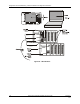


Diagnostics and Troubleshooting - External Indications of Diagnostic Information
120 HC900 Hybrid Controller Installation and User Guide Revision 5
9/03
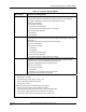
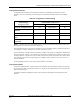
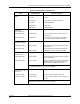
Table 24 - LED Indications on Scanner Module
LED LED State/Color Indicates Condition:
Scanner
Status
Off
Solid Red
Blinking Red
Solid Green
Blinking Green
No power.
Failed
(Diagnostic Code; refer to Table 30 - Scanner
Diagnostics.)
Startup Mode
Scan Mode
Green (On/Off)
Green (On/Off)
On while a message is being sent from the Main
CPU; otherwise Off.
On while the Main CPU is receiving a message.
Remains On as long as host is present; Off
when the host is removed from the link.
10Base-T port
(I/O Expansion –C50
CPU only)
XMT (upper LED)
LINK (lower LED)
NOTE: These LEDs indicate activity on the communication port, they are
controlled by hardware (PHY chip), not by software.
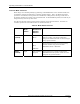
Table 25 - LED Indications on I/O Module
LED LED State/Color Indicates Condition:
Module Status Off
Solid Red
Blinking Red
Blinking Yellow
Solid green
Blinking Green
No power.
Hardware failure
Diagnostic Code; refer to Table 28 - Bad
Module Diagnostics.
At least one output is Forced.
Cold start with passing diagnostics
Normal scanning
Channel LEDs
(one per input or
output)
Green (On/Off)
For Inputs, indicates On or Off status of the field
input even if Forced to the opposite state.
For Outputs, indicates On or Off status of the
output including if Forced.