
HC900 Hybrid Controller Installation and User Guide


Appendix B Installation of Remote Termination Panels (RTPs) - Digital Input/Digital Output/Analog Output
Revision 5 HC900 Hybrid Controller Installation and User Guide 199
9/03
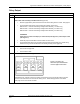
16 Point AC Digital Input
Step Action
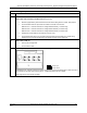
2 Mount RTP to DIN rail.
• Latch to rail. See page 205.
• Connect cable to RTP
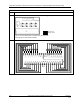
3 Set/verify jumper positions as shown.
Jumper open
Jumper closed
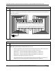
Module Removal / Insertion Under Power (RIUP) is supported by turning off Switch SW1 to allow removal of
the module from the rack without causing an arc. Please see page 62 for more details.
See page 203 for RTP internal schematic.
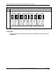
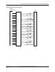
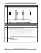
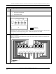
4 Connect field wiring.
Note: S-L1 in the wiring figure below refers to power that is disconnected from these screw terminals when
switch SW1 is open (0).
1 2 3 4 5 6 7 8 9 10 11 12 13 14 15 16 17 18 19 20
21 22 23 24 25 26 27 28 29 30 31 32 33 34 35 36 37 38 39 40
IN1
IN2
IN3
IN4
IN5
IN6
IN7
IN8
IN9
IN10
IN11
IN12
IN13
IN14
IN15
IN16
L2
I
N
1
+
I
N
2
+
I
N
9
+
I
N
1
0
+
I
N
5
+
I
N
6
+
L
2
I
N
3
+
I
N
4
+
I
N
7
+
I
N
8
+
L
2
L
2
L
2
I
N
1
1
+
I
N
1
2
+
I
N
1
3
+
I
N
1
4
+
I
N
1
5
+
I
N
1
6
+
S
-
L
1
S
-
L
1
L
1
S
-
L
1
S
-
L
1
S
-
L
1
S
-
L
1
S
-
L
1
S
-
L
1
S
-
L
1
S
-
L
1
S
-
L
1
S
-
L
1
S
-
L
1
S
-
L
1
S
-
L
1
S
-
L
1
S
-
L
1
S
-
L
1
S
-
L
1
L1