
HC900 Hybrid Controller Installation and User Guide


Pre-Installation Planning - Orientation of Rack Mounting
Revision 5 HC900 Hybrid Controller Installation and User Guide 39
9/03
The HC900 Controller must be mounted in suitable equipment enclosures. That is, all components such as
the Controller rack, IO Expander Racks, and the Operator Interface manufactured by Honeywell must be
mounted in approved furniture designed for industrial applications.
Orientation of Rack Mounting
Racks must be mounted as indicated in illustrations throughout this manual, so as to provide for vertical
airflow through the racks. That is, racks must never be mounted vertically, and must never be mounted
with the backplane horizontal (for example, flat on a horizontal panel or tabletop). Environmental
specifications apply only to the normal mounting configuration.
Heat Rise De-rating
The HC900 is rated to operate at 60
o
C. However, for maximum reliability, the following guidelines should
be observed for applications above 52
o
C.
1. Locate lower-power modules (Analog Input , Contact Input, etc) beside the Controller Module, and
keep higher-power modules (AC Output, AC Input, etc) away from the Controller Module. For power
consumption of each module, refer to Table 7.
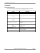
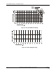
2. For 240 Vac applications and temperatures above 56
o
C, or 264Vac, 52
o
C , de-rate the number of ON
inputs per AC input module. (See AC Input de-rating data, see Figure 18.)
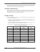
3. Limit the number of Analog Output modules to a maximum of 10 per rack. . (See Figure 19.)
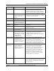
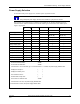
Table 7 - Power Applied, by Module Type
Module
HC900 Controller
Power (Watts)
Field Power
(Watts)
Total Power
(Watts)
Controller 2.3 0.0 2.3
Analog Input 1.0 0.0 1.0
Analog Output 4.3 0.0 4.3
Contact Input 2.0 0.0 2.0
Relay Output 2.4 0.0 2.4
DC In (@ 24V) 1.0 2.6 3.6
DC In (@ 32V) 1.0 5.1 6.1
DC Out 2.3 1.2 3.5
AC In (@120V) 1.0 1.9 2.9
AC In (@ 240V) 1.0 7.7 8.7
AC Out 1.0 12.0 13.0