Day/Night Camera NTSC PAL HCD484E HCD485EX HCD484EX User Guide Document 900.0355 – 01/06 – Rev 1.
Revision Issue Date Revisions 1.00 11/05 New document. 1.01 01/06 Minor corrections and updated illustrations. Rev 1.01 ii 900.
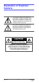
Explanation of Graphical Symbols This symbol indicates the presence of uninsulated “dangerous voltage” within the product’s enclosure that may be of sufficient magnitude to constitute a risk of electric shock to persons. This symbol indicates the presence of important operating and maintenance (servicing) instruction in the literature accompanying the product. CAUTION RISK OF ELECTRIC SHOCK DO NOT OPEN CAUTION: TO REDUCE THE RISK OF ELECTRIC SHOCK, DO NOT REMOVE THE COVER (OR BACK).
Warnings Installation and servicing should be performed only by qualified and experienced personnel. For outdoor applications, use an appropriate protecting housing conforming to IP65. To prevent fire or shock hazard, do not expose this camera to rain or moisture. Safeguards This camera is designed for use in general-purpose indoor CCTV applications and no other purpose. Only operate your camera between the temperature of -10°C to +50°C (14°F to 122°F).
Regulatory Notice INTENDED PURPOSE: SECURITY AND SURVEILLANCE CCTV APPLICATIONS. The product must be installed and maintained in accordance with good installation practice to enable the product to function as intended and to prevent problems. Refer to Honeywell Video Systems for installation guidance. Manufacturer’s Declaration of Conformance FCC Statement (U.S.A.) This device complies with Part 15 of the FCC Rules.
Rev 1.01 vi 900.
Contents Introduction . . . . . . . . . . . . . . . . . . . . . . . . . . . . . . . . . . . . 1 Features . . . . . . . . . . . . . . . . . . . . . . . . . . . . . . . . . . . . . . 1 Package Contents . . . . . . . . . . . . . . . . . . . . . . . . . . . . . . 2 Connecting Cables . . . . . . . . . . . . . . . . . . . . . . . . . . . . . . . 3 Connecting the Power Cable . . . . . . . . . . . . . . . . . . . . . 3 Main Power Model (100 VAC ~ 240 VAC, 50 Hz) . . . 3 Dual Power Model (12 VDC / 24 VAC) . . . . .
Troubleshooting . . . . . . . . . . . . . . . . . . . . . . . . . . . . . . . . 18 Service and Support . . . . . . . . . . . . . . . . . . . . . . . . . . . . . 19 Service and Support . . . . . . . . . . . . . . . . . . . . . . . . . . . 19 Limited Warranty . . . . . . . . . . . . . . . . . . . . . . . . . . . . . . 19 Specifications . . . . . . . . . . . . . . . . . . . . . . . . . . . . . . . . . . 20 General Specifications . . . . . . . . . . . . . . . . . . . . . . . . . 20 Functional Specifications . .
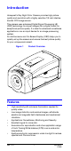
Introduction Honeywell’s Day Night Color Camera provides high picture quality and resolution with a highly sensitive 1/3 inch interline transfer CCD image sensor. This camera uses advanced Digital Signal Processing LSI (DSP) technology to convert images into a digital format for exceptional picture quality. It is ideal for advanced surveillance applications or as an input device for an image processing system.
• • • • Automatic electronic shutter provides > 1,600:1, equivalent to 40 steps, dynamic range to correct exposure, if a manual iris lens is used. Built-in functions: • On-Screen-Display (OSD) digital control. • Internal and line lock synchronization. • Auto Iris (AI) / Auto Electronic Shutter (AES). • Auto Iris level adjustment by digital process, manual adjustment on OSD. • Six options for full application of Back Light Conversion (BLC). • Advanced parameter adjustment for application conditions.
Connecting Cables Note Installation should only be done by qualified service personnel or system installers. Note Ensure that power to the camera is OFF before handling the power cable, regardless of whether the AC main power or low voltage 12 VDC / 24 VAC is used. Connecting the Power Cable Main Power Model (100 VAC ~ 240 VAC, 50 Hz) 1. Connect the AC power cord (supplied) firmly to the power cord socket of the camera. Figure 2 Main Power Model Power input 100 VAC ~ 240 VAC 2.
Dual Power Model (12 VDC / 24 VAC) This model has an AC/DC compatible input terminal. Either a 12 VDC or 24 VAC power supply cable can be connected to this terminal. The camera automatically detects the power source. Recommended wire gauge Solid wire: F 1.2 mm (AWG16), Stranded wire: 0.25 mm (AWG16), Element wire: F 0.18 Min. 1. Connect the power cable to the AC/DC compatible input terminal on the rear panel of the camera.
Type of Coaxial Cable RG-59/U RG-6U RG-11/U RG-15/U 3C-2V 5C-2V 7C-2V 10C-2V 500 600 800 1650 1980 2640 Recommended m 250 Maximum ft 825 Cable Length Wiring Precautions • • • Do not bend the coaxial into a curve with a radius smaller than 10 times the cable’s diameter. Never staple the cable even if using circular staples. Impendance mismatching will occur. Never crush or pinch the cable. This may cause poor picture quality.
Lens Installation The Day Night Color Camera supports Manual Iris Lens, Video Iris Lens and DC Auto Iris Lens installation. Use of the Honeywell IR Corrected Vari-focal Lens or DC Auto Iris Day Night Lens is recommended for outdoor applications to preserve an in-focus image in daytime and at night. Installing Video Auto Iris Lens The connection terminal is on the rear panel of the camera. Refer to Figure 5 for the necessary pin assignment to ensure correct operation. Recommended wire gauge size F 0.
Mounting the Lens 1. 2. Mount the lens by turning it clockwise on the lens mount of the camera. Connect the lens cable to the auto iris lens connector on the rear panel of the camera. Caution The lens mount used should be a CS-Mount (1”-32UN) and the lens weight should be less than 450 g (0.99 lbs). Focus and Back Focal Adjustment The following adjustment should only be done by qualified service personnel or system installers. 1. Loosen the back focus adjustment screw on the topside of the front head.
OSD Menu Operation Figure 8 OSD Menu Flow Chart Top Menu Second Menu Third Menu Sync INT * LL V-Phase Shutter AES 1/60 (1/50) * 1/100 (1/120) 1/250 1/500 1/1K 1/2K 1/4K 1/10K Lens Bright BF BLC Off * Center 1 Center 2 Door Way 1 Door Way 2 Low Half Up Half Configure Pedestal AGC White Bal Level H-APT Level V-APT Level 0.45 * 0.
Tact Switch Operation This camera uses a Set Up Menu that is displayed on a connected monitor. To set items in the Set Up Menu, use the following buttons located in the side panel. Figure 9 Side Panel Buttons Up Set Key Right Left Down Up Key This button is used to move the cursor upwards. Down Key This button is used to move the cursor downwards. Right Key This button is used to move the cursor to the right. Use this button to select or adjust the parameters of the selected item.
2. 3. 4. Check the current settings on the menu. Change the menu settings as necessary for your application. Refer to the following sections for detailed descriptions of the menu items. If you decide not to make any changes after checking the current settings, close the Set Up Menu and return to a normal camera picture by moving the cursor ( ) to EXIT and pressing SET.
Function Operations Synchronization Setting (SYNC) You can select internal sync mode (INT) or line-lock mode (LL). 1. 2. Use the Up and Down keys to move the cursor ( ) to the Sync parameter and use the Right and Left keys to select line-lock (LL) or internal (INT). If LL is selected, press SET and the Line Lock menu appears. If INT is selected, the synchronization mode is automatically set to internal sync and the menu displays INT.
Lens Bright Setting This item is used to adjust the brightness level of the auto iris lens drive which is supplied for the DC drive lens or video iris lens. Before operation make sure that the correct connection is made to the video auto iris lens or DC auto iris lens. 1. 2. Move the cursor to the Lens parameter, select Bright and press SET. The Bright Level menu appears on the monitor. Use the Right and Left keys to adjust the I cursor to open (+) or close (–).
Figure 11 BLC Compensation Areas Detect Area Detect Area CENTER 1 CENTER 2 Detect Area Detect Area DOORWAY 1 LOW HALF Detect Area Detect Area DOORWAY 2 UP HALF Configure Aperture 1. 2. Move the cursor ( ) to Aperture and press SET. The Aperture Configure Menu will appear. Move the I cursor to adjust the V-Aperture and HAperture level. Gamma 1. 2. Move the cursor ( ) to Gamma and press SET. The Gamma Configure Menu will appear. Use the Left and Right keys to select a Gamma level of 0.45, 0.
AGC 1. 2. Move the cursor ( ) to AGC and press SET. The AGC Configure Menu will appear. Use the Left and Right keys to select one of the following AGC values: • Select one of the 7 limited values (18dB, 22dB, 26dB, 30dB, 32dB, 34dB, 36dB) to limit the enhanced gain of the AGC circuit. • Select OFF to close the AGC function. • Select Sens Up to use a maximum value (38dB) of AGC gain. CAM Title The camera provides text generation on the display monitor.
3. 4. Press SET to start the white balance tracing. When the white balance tracing is completed, release the SET key and remove the white surface from in front of the camera. D/N This function allows the camera to automatically switch from a color camera to B/W camera by either auto detecting the luminance, manual switching, or by the external contact terminal’s IR Lamp connection on the camera rear panel. Fuzzy The camera switches to a B/W camera by auto detecting luminance.
Provide a 000 ~ 999 ID address and a 3-digit password to protect the RS485 setting. Use the arrow keys to move the cursor to RS485 and press SET to open the RS485 Menu. Password Setting Before opening the RS485 menu, the camera system will request the 3-digit password. Input the correct password, select OK and press SET to open the RS485 menu. Note The factory default password is 000. We recommend changing the password immediately to prevent tampering. To change the password: 1. 2. 3.
Care and Maintenance Do not disassemble the camera To prevent electric shock, do not remove screws, case or covers. There are no user-serviceable parts inside. Service should be performed only by qualified service personnel. Handle the camera with care Avoid damage by improper handling (striking, shaking) or storage. Do not expose the camera to rain or moisture or operate it in wet areas Take immediate action if the camera becomes wet. Turn the power OFF and refer servicing to qualified service personnel.
Troubleshooting If this happens … Try this … No power / LED not lit • • Check the power connections. Verify that the power supply is working. (Use a camera that is known to be good.) No video • • Check power connections. Check BNC connections. (Use a camera that is known to be good.) Check the lens. Remove the lens. If video is present, the lens is the source of problem. • Power applied but picture is black • Video iris • • • • • • DC Iris.
Service and Support Service and Support Refer servicing to qualified personnel or contact Honeywell Technical Support at +1.800.796.CCTV for assistance. Limited Warranty Honeywell International Inc. (“Seller”), warrants this camera to be in conformance with its own plans and specifications and to be free from defects in materials and workmanship under normal use and service for a period of up to two (2) years from the date of manufacture.
Specifications General Specifications General Image Size: HCD484E / HCD484EX / HCD485EX 1/3” Format Interline CCD sensor Pixel Element: HCD484EX / HCD485EX: 752 (H) x 582 (V) approx. (H) x (V) 440K Pixels HCD484E: 768 (H) x 494 (V) approx.
Functional Specifications Functional Specifications Auto IRIS Control: Video Drive / DC Drive Separate Output * Day & Night: Optical Low Pass Filter Removable * External Day Night Control: External Relay Contact for GND Loop Chroma Separate: CS / Color Killer * Color Killer: ON / OFF / Fuzzy SYNC System: INT / Line Lock Line Lock: Phase Adjust Range: 0° ~ 280° Frequency Range: PAL 50 Hz ± 1 Hz / NTSC 60 Hz ± 1 Hz Remote Controller: RS-485 two way communications Camera Addressable: 000 ~ 999
Function Control Specifications (Cont’d) Exposure Control: Auto Electronics Shutter / Manual Electronics Shutter / Auto IRIS Lens Auto Electronics Shutter: Max, Limit and Level Adjustable Menu Electronics Shutter: 8 Step: 1/50 (1/60), 1/120 (1/100), 1/250, 1/500, 1/1000, 1/2000, 1/4000, 1/10000 Auto IRIS Lens Driver: Video IRIS Lens / DC IRIS Lens Lens Level Control: Both for DC IRIS Lens and Video IRIS Lens BLC: White Balance Control: 6 Area Select and Level Adjustment; Center 1, Center 2, Door
Honeywell Video Systems (Head office) 2700 Blankenbaker Pkwy, Suite 150 Louisville, KY 40299, USA www.honeywellvideo.com ℡ +1.800.796.2288 Honeywell Security Australia Pty Ltd. Unit 5, Riverside Centre 24-28 River Road West Parramatta, NSW 2150, Australia www.ademco.com.au ℡ +61.2.8837.9300 Honeywell Security Asia Pacific 33/F Tower A, City Center, 100 Zun Yi Road Shanghai 200051, China www.security.honeywell.com/cn ℡ +86 21.2527.