Premium Vandal Dome Camera NTSC / PAL HD28C4HR6 HD28C4HR6X HD28C4HR9 HD28C4HR9X HD28W4HR6 HD28W4HR6X HD28W4HR9 HD28W4HR9X HD28D4HR6 HD28D4HR6X HD28D4HR9 HD28D4HR9X Installation Guide Document 900.0275 – 10/05 – Rev 1.
Revisions Issue Date Revisions 1.00 09/05 New document. 1.01 10/05 Changed HD28R to HD28 throughout, removed utp & fiber termination boards updated back cover. Rev 1.01 ii Document 900.
Warnings Installation and servicing should be performed only by qualified and experienced technicians to conform to all local codes and to maintain your warranty. WARNING! The use of CSA Certified/UL Listed Class 2 power adapters is required to ensure compliance with electrical safety standards. WEEE (Waste Electrical and Electronic Equipment). Correct disposal of this product (applicable in the European Union and other European countries with separate collection systems).
FCC Compliance Statement Information to the User: This equipment has been tested and found to comply with the limits for a Class A digital device. Pursuant to Part 15 of the FCC Rules, these limits are designed to provide reasonable protection against harmful interference when the equipment is operated in a commercial environment.
Contents Introduction . . . . . . . . . . . . . . . . . . . . . . . . . . . . . . . . . . . . . . . . . . . . 1 Before You Begin . . . . . . . . . . . . . . . . . . . . . . . . . . . . . . . . . . . . . . .1 Unpack Everything . . . . . . . . . . . . . . . . . . . . . . . . . . . . . . . . . . . .1 Equipment Required . . . . . . . . . . . . . . . . . . . . . . . . . . . . . . . . . .1 Installation . . . . . . . . . . . . . . . . . . . . . . . . . . . . . . . . . . . . . . . . . . . . 2 Mounting the Camera .
Introduction The HD28 Series is Honeywell’s premium line of vandal-resistant, fully-integrated CCTV cameras. The HD28 series enclosure is designed for easy installation and setup. Before You Begin Please read this guide carefully before you install the HD28 series camera. Keep this guide for future reference. Unpack Everything Check that the items received match those listed on the order form and packing slip.
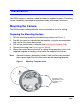
Installation Your HD28 camera is weather-sealed for indoor or outdoor locations. The wiring can be completely concealed for maximum vandal and tamper resistance. Mounting the Camera The HD28 camera is designed to be surface mounted on a wall or ceiling. Preparing the Mounting Surface 1. 2. 3. 4. 5. Affix the mounting template to the mounting surface (see Figure 1). Pre-drill four holes as indicated on the template, using the recommended hole size for the screws being used.
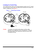
Installing the Conduit Plug Your HD28 enclosure comes with a conduit plug pre-installed in the 1/2” conduit entry on the back of the housing. This plug may be removed and installed in the side 3/4” conduit entry (see Figure 2). Figure 2 Conduit Plug Installation Back View Side View Screw Retainer plate Gasket Caution Rev 1.01 Conduit plug If a conduit is not used for cable routing, install the rubber grommet in the conduit hole, then slit the grommet and feed the wiring through.
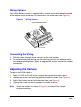
Wiring Options Your HD28 Series camera is supplied with a coaxial termination board mounted to the bottom of the enclosure. All connections are made here (see Figure 3). Figure 3 Wiring Options Coax Termination Board Video Audio Power Case/ Not used Ground Connecting the Wiring 1. 2. Pull the cables through either the back or the side conduit. To minimize moisture leaking into the housing, position the enclosure with the conduit pointing down. Apply an appropriate sealant around the conduit connection.
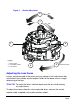
Figure 4 Gimbal Adjustment 3 Tilt 1 Pan 1 3 Legend 1 = Pan rotation 2 = Horizontal rotation 3 = Tilt rotation 2 2 Horizontal rotation Adjusting the Lens Focus Lenses are pre-focused at the factory but may require a final adjustment after installation in the unlikely event the optical effect of the dome causes a slight defocusing of the lens. TECH TIP! To check the focus, hold the dome over the lens while making any adjustments.
Dip Switch Functions (Color Cameras, Including TDN Models) Follow Figure 5 to set the dip switches on a color camera. Color Camera Switch Settings AE FLON BLC IRIS N/A * AGC MAX AWB1 AWB2 AWB3 * Not used. Leave in Off position. Push lock GAMMA Figure 5 1 2 3 4 5 6 7 8 9 10 Upper locking screw to set focus ON OFF Video monitor output Lower locking screw to set focal length Auto Iris Level Adj. (Varifocal lens). Turn screw clockwise to increase brightness level.
Adjustment Method (Color Cameras) Switch no. Function Off On 1 GAMMA Off (0.45) On (1.
Manually Setting Shutter Speed (Color Cameras) To manually set the shutter speed, turn switch #2 to the ON position; then set switch #3, #4, and #5 for the desired shutter speed (see Figure 5).
Dip switch functions (WDR cameras) Wide Dynamic Range Camera Switch Settings Line-lock adjustment EE/DC IRIS AWB/ATW WDR AGC MIRROR Figure 6 Upper locking screw to set focus Auto Iris level adjustment. If necessary, turn clockwise to increase brightness level.
Adjusting the Line Lock (Vertical Phase) for 24 VAC Operation Phase adjustment may be necessary in multiple camera installations to prevent picture roll when switching between two cameras. To adjust the vertical phase while switching between two cameras, turn the Line lock adjustment screw on one camera until there is no vertical roll. See Figure 5 for color cameras. The Wide Dynamic Range cameras use line lock adjustment buttons to adjust the vertical phase (see Figure 6).
Routine Maintenance Use regular liquid cleaners to remove dirt and grime from the dome. Caution Do not use harsh or abrasive cleaners which can scratch the polycarbonate dome and reduce visibility for the camera. If the camera view is obstructed by scratches, remove the front plate and rotate to find an unscratched part of the dome. Troubleshooting No video Check: • Power supply voltage is within the operating specifications for your camera model (see Troubleshooting).
Warranty and Service Subject to the terms and conditions listed on the product warranty, during the warranty period Honeywell will repair or replace, at its sole option, free of charge, any defective products returned prepaid. In the event you have a problem with any Honeywell product, please call Customer Service at 1.800.796.2288 for assistance or to request a Return Merchandise Authorization (RMA) number.
Specifications Note Specifications apply to all camera models, unless otherwise noted.
Cable Guidelines Power supply cable maximum length (feet/meters) Cameras with AC/DC power supplies Wire gauge Power supply 24 AWG 22 AWG 18 AWG 16 AWG 15 VDC 45/14 73/22 185/56 295/90 24 VAC 408/125 660/201 1674/510 2664/812 Note Calculations are based on an unregulated linear power supply which would be the worst case. Using a regulated or switching power supply can increase the cable distance.
Honeywell Video Systems (Head Office) 2700 Blankenbaker Pkwy, Suite 150 Louisville, KY 40299, USA www.honeywellvideo.com ℡ +1.800.796.2288 Honeywell Security Australia Pty Ltd. Unit 5, Riverside Centre, 24-28 River Road West Parramatta, NSW 2150, Australia www.ademco.com.au ℡ +61.2.8837.9300 Honeywell Video Systems UK Ltd. Aston Fields Road, Whitehouse Ind Est Runcorn, Cheshire, WA7 3DL, UK www.security.honeywell.com ℡ +44.1928.754.