
Operation Manual


800-21090V2 - A - 03/2016
A
Connecting Alarm Input/Outputs A
This appendix contains the following sections:
• Before Connecting Alarm Inputs and Outputs, page 161
• Alarm Input and Output Rear Panel Connections, page 161
• Guidelines for Connecting Local Alarm Input Ports, page 162
• Guidelines for Connecting Alarm Output Ports, page 162
Before Connecting Alarm Inputs and Outputs
• Ensure that the alarm input mode is set to ground.
• Ensure that the signal is grounded.
• Know that the alarm inputs require low-level voltage signals.
• Ensure that the alarm input mode is set to either NC (normally closed) or NO (normally
open).
• Use a relay if you are connecting two NVRs, or a NVR plus another device, to separate them.
• Do NOT directly connect the alarm output port to a high-power load. The load should be
less than 1 A to avoid damage.
•Use the
contactor
to make the connection between the alarm output port and the load.
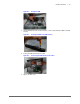
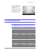
Alarm Input and Output Rear Panel Connections
The connections for the alarm input and output channels are described below:
Input/Output Description
1 to 4 Alarms inputs 1 to 4. The inputs becomes active with low voltage.
NO1 C1, NO2 C2 Normally open activation outputs (on/off)
Ground