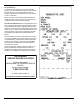
Owner’s Manual For Spark-Ignited Stationary Emergency Generators Residential and Commercial 22 kW 25 kW 27 kW 30 kW 32 kW 36 kW 38 kW 45 kW 48 kW 60 kW * * NOT INTENDED FOR USE IN CRITICAL LIFE SUPPORT APPLICATIONS. * DEADLY EXHAUST FUMES! OUTDOOR INSTALLATION ONLY! 2.4L 1.5L 2.4L 1.5L 2.4L 2.4L 2.4L 2.4L 5.4L 2.4L ONLY QUALIFIED ELECTRICIANS OR CONTRACTORS SHOULD ATTEMPT INSTALLATION! This manual should remain with the unit.
Use this page to record important information about the generator set. For quick and easy reference, copy the information printed on the Unit Identification Label onto the sample label printed here. The Unit Identification Label is located on the base frame adjacent to the front engine mount on all models. When contacting an Independent Authorized Service Dealer about parts and/or service, always provide the complete model number and serial number.
Table of Contents Table of Contents Section 1 Safety 1.1 Introduction .......................................................................................................................... 1 1.2 Safety Information ................................................................................................................ 2 1.3 General Hazards ................................................................................................................... 2 1.4 Exhaust Hazards ...................
Table of Contents Section 4 Operation 4.1 Control Panel ......................................................................................................................19 4.2 Auto/Manual/Off ..................................................................................................................19 4.3 Menu Navigation .................................................................................................................20 4.4 Alarm/Warning Conditions ................................
Table of Contents 5.7 Schedule A Maintenance ................................................................................................... 31 5.7.1 Schedule A Maintenance Item Locations ................................................................................... 31 5.7.2 Preliminary Instructions .............................................................................................................. 31 5.7.3 Check Enclosure Louvers .........................................................
Table of Contents WARNING California Proposition 65. Engine exhaust and some of its constituents are known to the state of California to cause cancer, birth defects, and other reproductive harm. (000004) WARNING California Proposition 65. This product contains or emits chemicals known to the state of California to cause cancer, birth defects, and other reproductive harm.
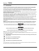
Section 1 Safety 1.1 — Introduction Thank you for purchasing this stationary automatic standby generator set. Every effort was made to ensure that the information in this manual was both accurate and complete at the time it was released. However, the manufacturer reserves the right to change, alter or otherwise improve this product at any time without prior notice. This generator is designed to automatically supply electrical power to operate critical loads during a utility power failure.
Safety 1.2 — Safety Information Study these safety rules carefully before operating or servicing this equipment. Become familiar with this Owner’s Manual and with the unit. The generator can operate safely, efficiently and reliably only if it is properly installed, operated and maintained. Many accidents are caused by failing to follow simple rules or precautions. The manufacturer cannot anticipate every possible circumstance that might involve a hazard.
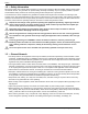
Safety 1.4 — Exhaust Hazards • Generator engine exhaust contains DEADLY carbon monoxide, an odorless, colorless, poisonous gas. Breathing carbon monoxide can cause dizziness, throbbing temples, nausea, muscular twitching, headache, vomiting, weakness, sleepiness, inability to think clearly, fainting, unconsciousness or even death. If any carbon monoxide poisoning symptom is experienced, move into fresh air and immediately seek medical attention. • This generator is designed for OUTDOOR installation ONLY.
Safety This page intentionally left blank.
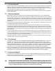
Section 2 Specifications 2.1 — Emission Information The U.S. Environmental Protection Agency (EPA) requires that the generator comply with exhaust emission standards. The generator is certified to meet the applicable EPA emission levels, and is certified for use as a stationary engine for standby power generation. Any other use may be a violation of federal and/or local laws.
Specifications 2.2 — Specifications Model 22 kW 25 kW 27 kW 30 kW 32 kW 36 kW 38 kW 45 kW 48 kW 60 kW Engine 2.4L 1.5L 2.4L 1.5L 2.4L 2.4L 2.4L 2.4L 5.4L 2.
Specifications Model 22 kW 25 kW 27 kW 30 kW Engine 2.4L 1.5L 2.4L 1.5L Breather Closed Exhaust Flow at Rated Output 60 Hz Exhaust Temperature at Rated Output 32 kW 36 kW 38 kW 45 kW 48 kW 2.4L 5.4L 2.4L 2.4L 2.4L Open Closed Open 60 kW 2.
Specifications 2.4 — Weather and Maintenance Kits To keep the generator running at its peak, the following kits are offered: • Cold Weather Kit – Recommended for climates with temperatures below 32°F • Extreme Cold Weather Kit – Recommended Block Heater Kit for protection in temperatures below 32°F • Scheduled Maintenance Kit – Kit includes the recommended parts to maintain the generator. Refer to the Service Schedule for regular maintenance intervals.
Specifications 2.7 — Reconfiguring the Fuel System While some models are created fuel specific for either Natural gas (NG) or Liquid Propane vapor (LPV) and are not fuel convertible, others are configured at the factory for NG, but are field convertible to LPV. Units fitted with a dual fuel carburetion system are generally configured for the selected fuel source during installation.
Specifications * Serious injury, including death, or damage will occur if not configured properly. Consult an Authorized Dealer with any questions. 2.7.2— Change Fuel Selection Failure to convert both the hardware and software will result in decreased performance and an increase in emissions, which is a violation of Environmental Protection Agency (EPA) regulations. It is the responsibility of the installer to make sure that only the correct recommended fuel is supplied to the generator fuel system.
Section 3 Activation and Startup 3.1 — Orientation NOTE: The 2.4L (32 kW) unit is depicted in the artwork used in this manual. The location and appearance of some components may vary between engine models. The side of the enclosure with the viewing window is identified as the rear of the generator set. The right and left sides are identified by standing at the rear and looking towards the front of the unit. Viewing Window Battery Figure 3-1. Enclosure (Rear Left View) 3.
Activation and Startup 3.3 — Install Battery $ CAUTION: Always connect the positive battery cable first. If the positive cable should contact ground with the negative cable installed, the resulting sparks may cause a battery explosion which could result in serious injury. 1. Loosen two screws with nylon washers to release holddown clamp from battery tray. 2. Install battery onto tray. 3. Install two screws with nylon washers to secure holddown clamp to battery tray. 4.
Activation and Startup 3.5 — Activate Unit Display Reads: Up Arrow = (+) Language - English + Generator Active is displayed on the LCD screen when the unit is first powered up. After displaying firmware and hardware version codes, as well as other system information, the Installation Wizard is launched, and the Language screen is displayed. If the wrong language is selected, it may be changed later using the Edit menu. Use UP ARROW or DOWN ARROW to scroll to desired language. Press ENTER.
Activation and Startup Display Reads: Use UP ARROW or DOWN ARROW to select either Yes or No. Quiet Test Mode? Yes No Select YES to perform exercise at low speed. Select NO to perform exercise at normal operating speed. Press ENTER. Display Reads: Set Exercise Time. Select Hour (0-23) -1+ Use UP ARROW or DOWN ARROW to increment or decrement the hour. Press ENTER. In the AUTO mode, the engine starts and runs once each week at the time and day specified.
Activation and Startup 3.7 — Operational Checks + The following procedures require special tools and skills. Contact an authorized service provider to perform these tasks. 3.7.1— Self Test Upon power up, the controller goes through a system self test which checks for the presence of utility voltage on the DC circuits. This is done to prevent damage if the installer mistakenly connects AC utility power sense wires into the DC terminal block.
Activation and Startup 9. + Allow the engine to warm up for about five minutes. Move the Main Circuit Breaker switch on the generator control panel up to the ON (or closed) position. Generator power voltage is now supplied to the transfer switch. Contact with live transfer switch parts will result in dangerous and possibly fatal electrical shock. 10. Connect an accurate AC voltmeter and a frequency meter across transfer switch terminal lugs E1, E2, and E3 (if three phase). 11.
Activation and Startup 1. Verify that the generator is OFF. A red LED on the control panel illuminates to confirm that the system is in the OFF mode. 2. Install front cover of the transfer switch. 3. Turn ON the utility power supply to the transfer switch, using the means provided (such as a utility main line circuit breaker). NOTE: Transfer Switch will transfer back to utility position. 4. Move the Main Circuit Breaker switch on the generator control panel up to the ON (or closed) position. 5.
Activation and Startup This page intentionally left blank.
Section 4 Operation 4.1 — Control Panel NOTE: The control panel is intended for use by qualified service personnel only. The control panel is located behind the viewing window at the rear of the unit. * With the control panel set to AUTO, the engine may crank and start at any time without warning. Such automatic starting occurs during the programmed exercise cycle or when utility power source voltage drops below the configured level.
Operation LCD Screen UP ARROW Green LED Blue LED Red LED ENTER AUTO MANUAL OFF DOWN ARROW ESCAPE Figure 4-2. Control Panel and LCD Screen 4.3 — Menu Navigation See Figure 4-3. Feature Description System Menus HOME Screen The system returns to the Home screen if the control panel is not used for five minutes. The screen normally displays a Status message, such as Ready to Run (Auto mode) or Switched to OFF (Off mode), and the total Hours of Protection.
Operation Feature Description Navigation ESCAPE ENTER UP ARROW DOWN ARROW Used to abort a routine or back up to the preceding menu. Used to make a selection or save an entry. Used to move forward or backward from menu to menu or to scroll forward or backward (increment or decrement) through available selections. NOTE: Pressing the control panel illuminates the backlight for 30 seconds. The backlight also illuminates for 30 seconds whenever an active Alarm/Warning message is displayed.
22 *Note: E-Codes Not Shown ALARM MESSAGE(S)* "High Engine Temp.
Operation Figure 4-3. Navigation Menu 4.4 — Alarm/Warning Conditions The owner/operator is alerted to Alarm and/or Warning conditions via the control panel LCD screen. All Alarm conditions cause the generator to shut down. The Warning messages alert the operator to conditions that do not disable the unit or require immediate correction. The possible Alarm/Warning messages are listed below.
Operation 4.6.2— User Programmable 4.6.2.1—Start-Up Delay Timer A programmable line interrupt delay (or Start-Up Delay) timer is provided. When utility voltage fails (falls below 60% of nominal), the start-up delay timer is started. If the voltage rises above the Utility Volts Low threshold, the timer is reset. If the utility voltage remains below the threshold during the duration of the timer, the unit cranks and starts.
Operation 4.9.1— Automatic Sequence of Operation 4.9.1.1—Utility Failure If the control panel is set to AUTO when the utility power fails, a ten second Start-Up Delay timer is started (user programmable). If utility power is still absent when the time expires, the engine cranks and starts. Once started, a five second engine Warm-Up Delay timer starts (user programmable). When the time has elapsed, the load is transferred to the generator.
Operation IMPORTANT NOTE: Always use the applicable transfer switch owner's manual for actual manual transfer switch operation instructions. The information presented here describes a transfer switch, which is not used for three phase applications. See specific manual for three phase transfer switch. 4.10.1— Transfer to Generator Power When utility power fails, manually transfer to standby power and start the generator as follows: 1. Press OFF on the control panel.
Section 5 Maintenance 5.1 — Component Locations The side of the enclosure with the viewing window is identified as the rear of the generator set. The right and left sides are identified by standing at the rear and looking towards the front of the unit. NOTE: The 2.4L (32 kW) unit is depicted in the artwork used in this manual. The location and appearance of some components may vary between engine models. Viewing Window 7.
Maintenance Coolant Overflow Reservoir Coolant Drain Spark Plugs Oil Drain Hose Battery Figure 5-3. Left Side View NOTE: All normal maintenance and service items are easily accessible for consumer convenience. Wherever possible, touch points are colored orange to provide for quick and easy recognition. 5.2 — Access Panels Access panels are located at both the left and right sides of the enclosure. 5.2.1— Removal 1. Insert key into latch and rotate counterclockwise 1/2 turn. See Figure 5-4. 2.
Maintenance 5.3 — Service Maintenance Intervals NOTE: Use only Genuine Generac parts to ensure warranty coverage. * nel only. All generator service must be performed by an authorized service provider or a qualified service person- It is important to perform all maintenance at the interval specified in the Service Maintenance Schedule. This ensures safe and proper operation, as well as compliance with applicable emissions standards.
Maintenance 5.4 — Remove From Service To ensure safety, follow the steps below prior to inspection, maintenance or service. IMPORTANT NOTE: If currently experiencing a utility outage, see Subsection 6.3 —Removal From Service During Utility Outages for special instructions. 1. Open the viewing window. See Subsection 3.4 —Open Viewing Window. 2. Move the Main Circuit Breaker switch down to the OFF (Open) position. See A of Figure 5-5. 3. Press OFF on the control panel.
Maintenance 5.7 — Schedule A Maintenance NOTE: Perform Schedule A maintenance once each year or after 125 hours of service, whichever comes first. NOTE: The 2.4L (32 kW) unit is depicted in the artwork used in this manual. For the general location of components in all other models, see Subsection 5.7.1—Schedule A Maintenance Item Locations. 5.7.1— Schedule A Maintenance Item Locations NOTE: The side of the enclosure with the viewing window is identified as the rear of the generator set.
Maintenance 5.7.5— Check Coolant Level and Hoses * 1. Do not add coolant when the engine is hot. Steam and scalding fluids can cause severe burns. Verify that the coolant level is between the HOT and COLD marks on the overflow reservoir. See Figure 5-6. NOTE: Coolant expands when hot, so the level may be higher than the HOT mark. Do not add coolant higher than the HOT mark. 2. If the coolant level is below the COLD mark, remove fill cap from overflow reservoir and add coolant. See Subsection 2.
Maintenance Verify that the oil level is at or near the FULL mark. Add oil as necessary. See A of Figure 5-7 7. NOTE: Observe the oil level on both sides of the dipstick. The lower of the two readings is the correct oil level measurement. 8. If necessary, remove the oil fill cap and slowly add oil. Do not fill above “FULL” mark on dipstick. 9. Install dipstick and oil fill cap. 10. Install battery negative cable (black) onto battery negative (-) terminal. 11.
Maintenance 2. Use one wrench to hold hex on hose fitting (to prevent rotation), and use second wrench to remove drain plug. * Hot oil may cause burns. Allow engine to cool before draining oil. Avoid prolonged or repeated skin exposure with used oil. Thoroughly wash exposed areas with soap 3. Drain oil into a suitable container. 4. Install drain plug onto end of oil drain hose. 5. Install oil drain hose into holding clamp. 6. Rotate oil filter counterclockwise to remove from oil filter adapter.
Maintenance A B Figure 5-8.
Maintenance Oil Fill Cap Air Cleaner Air Cleaner Oil Fill Cap Oil Filter Oil Level Dipstick Oil Filter 2.4L: 22/27/36/45 kW Oil Level Dipstick 2.4L: 32/38 kW Oil Fill Cap Oil Fill Cap Air Cleaner Air Cleaner Oil Filter Oil Filter Oil Level Dipstick 2.4L: 60 kW Oil Level Dipstick 1.5L: 25/30 kW Oil Fill Cap Oil Level Dipstick Air Cleaner Oil Filter 36 5.
Maintenance Figure 5-9. Engine Oil and Air Cleaner Maintenance (All Models) 5.7.9— Check Battery Condition/Fluid Level 5.7.9.1— Check Condition and Clean 1. Verify that top of battery is clean and dry. Dirt and electrolyte on top of the battery can cause battery to self-discharge. Clean battery top with a solution of baking soda (sodium bicarbonate) and water (5 teaspoons baking soda per quart or liter of water). When solution stops bubbling, rinse off the battery with clean water. 2.
Maintenance Installation $ Always connect the positive battery cable first. If the positive cable should contact ground with the negative cable installed, the resulting sparks may cause a battery explosion which could result in serious injury. 1. Install rubber protective cover over battery positive (+) terminal. See A of Figure 5-11 2. Grasp battery strap and lift battery. See B of Figure 5-11 3. Set battery onto battery tray. 4.
Maintenance Water Pump Pulley Belt Deflection Gauge Alternator Pulley 2.4L: Manual Adjustment Automatic Tensioner 1.5L: Manual Adjustment 5.4L: Automatic Adjustment Figure 5-12. Check Accessory/Drive Belt Deflection 5.7.11— Replace Air Filter Element 1. Remove wing nut, lock washer and flat washer from threaded rod to release air cleaner cover. See Figure 5-13 2. Remove the air filter element and discard. 3. Thoroughly clean air cleaner cover of any dust, dirt, or debris. 4.
Maintenance Element Cover Flat Washer Wing Nut Lock Washer Figure 5-13. Air Cleaner Cover and Filter Element NOTE: Service kits are available from Independent Authorized Service Dealers. 5.7.12— Final Instructions If only performing Schedule A maintenance procedures, proceed as follows: 40 1. Install battery negative cable (black) onto battery negative (-) terminal. 2. Install left and right side access panels. See Subsection 5.2 —Access Panels. 3. See Subsection 5.10 —Return To Service.
Maintenance 5.8 — Schedule B Maintenance NOTE: Perform Schedule B maintenance every two years or after 250 hours of service, whichever comes first. Before proceeding below, first perform all tasks listed under Schedule A Maintenance. NOTE: The 2.4L (32 kW) unit is depicted in the artwork used in this manual. For the general location of components in all other models, see Subsection 5.8.1—Schedule B Maintenance Item Locations. 5.8.
Maintenance 14. Insert funnel into filler neck of radiator. See B of Figure 5-14 15. Slowly pour coolant into filler neck until radiator is full. 16. Install radiator cap. 17. Press MANUAL on the control panel to start the engine. A blue LED illuminates to confirm that the system is in the MANUAL mode. 18. Allow engine to run until the thermostat opens, as indicated by heating of the top radiator hose. 19. Check coolant hoses for leaks. Tighten clamps, if necessary. 20.
Maintenance A B Figure 5-15. Adjust Spark Plug Gap 5. Check condition of threads in cylinder head and on spark plugs. If necessary, soften deposits with penetrating oil and clean out with a thread chaser. 6. Clean spark plugs using a wire brush and commercial solvent. Do not blast spark plugs. Use new spark plugs if necessary. 7. See B of Figure 5-15 Check spark plug gap using a wire feeler gauge.
Maintenance 5.9 — Schedule C Maintenance NOTE: Perform Schedule C maintenance after 1000 hours of service. Before proceeding below, first perform all tasks listed under Schedule A Maintenance and Schedule B Maintenance. * 1. 2. The following procedures require special tools and skills. Contact an authorized service provider to perform these tasks. Remove battery negative cable (black) from battery negative (-) terminal. Proceed as follows: • Replace Timing Belt (2.
Maintenance 5.11 — Lube Oil Maintainer System 5.11.1— Description NOTE: Oil reservoir is empty when shipped from factory. Fill with clean engine oil to activate the system. The 36 kW, 45 kW, and 60 kW models are equipped with a Lube Oil Maintainer System. The system is installed at the factory and calibrated at the factory to the correct engine-running crankcase oil level. As needed, the system keeps the engine lubricating oil full by automatically adding clean oil from the oil supply tank.
Maintenance 5.11.3— Test Functionality See A of Figure 5-17. Momentarily press the test button to confirm that the float is operating correctly. * filling the crankcase can result in engine damage. Do not hold the test button down for a prolonged period of time or the crankcase can be over filled. Over 5.11.4— Shutoff Valve See Figure 5-19 and Figure 5-20. When draining engine crankcase oil, always close shutoff valve to avoid draining clean oil from supply tank.
Section 6 Troubleshooting 6.1 — Engine Troubleshooting Problem The engine will not crank. The engine cranks but will not start. The engine starts hard and runs rough. The generator is set to OFF, but the engine continues to run. There is no AC output from the generator. There is no transfer to standby after utility source failure. Unit consumes large amounts of oil. Cause Correction Fuse blown. Replace 7.5 amp fuse in generator control panel. Correct short circuit condition if fuse blows again.
Troubleshooting 6.2 — Controller Troubleshooting Active Alarm NOT ACTIVATED Solution Unit will not start in AUTO with utility loss. Refer to activation section in Owner’s Manual. NONE Unit running in AUTO but no power in house. Check MLCB. Contact servicing dealer if MLCB is in the ON position. NONE Unit will not start in AUTO with utility loss. Check screen for start delay countdown. If the start up delay is greater than expected, contact servicing dealer to adjust from 2 to 1500 seconds.
Troubleshooting 6.3 — Removal From Service During Utility Outages If, during prolonged utility outages, the user wishes to remove the unit from service to conserve fuel, reduce run hours, or to perform maintenance tasks, then complete the steps listed below. IMPORTANT NOTE: Failure to abide by this procedure can result in equipment damage. To remove the generator from service while running in AUTO and online, proceed as follows: 1. Turn the main utility disconnect to OFF (Open). 2.
Troubleshooting NOTE: On 36 kW, 45 kW, and 60 kW models, close shutoff valve to avoid draining the oil supply tank with the crankcase oil. For more information, see Subsection 5.11 —Lube Oil Maintainer System. 11. Remove oil drain hose from holding clamp. 12. Use one wrench to hold hex on hose fitting (to prevent rotation), and use second wrench to remove drain plug. 13. Drain oil into a suitable container. 14. Install drain plug onto end of oil drain hose. 15.
Troubleshooting 12. Press MANUAL on the control panel to start the engine. A blue LED illuminates to confirm that the system is in the MANUAL mode. 13. Allow the engine to run until it is reaches normal operating temperature. Check for leaks while the engine is running. 14. Press OFF on the control panel. A red LED illuminates to confirm that the system is in the OFF mode. 15. Install left and right side access panels. See Subsection 5.2 —Access Panels. 16.
Troubleshooting This page intentionally left blank.
This page intentionally left blank.
Part No. 0K8185 Rev. A 02/16/2015 Printed in USA ©2015 Generac Power Systems, Inc. All rights reserved Specifications are subject to change without notice. No reproduction allowed in any form without prior written consent from Generac Power Systems, Inc. Generac Power Systems, Inc. S45 W29290 Hwy. 59 Waukesha, WI 53189 1-888-GENERAC (1-888-436-3722) generac.