
Installation Instructions


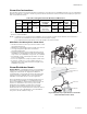


Table Of Contents
- Introduction
- Sizing
- Location
- Mounting the Humidifier
- Plumbing
- Electrical
- Start Up
- Operation
- Maintenance and Servicing
- Replacement Parts
- Cylinder Replacement Kit
- Control Board Replacement
- Troubleshooting
- 5 Year Warranty
- INTRODUCTION
- DIMENSIONNEMENT
- EMPLACEMENT
- MONTAGE DE L’HUMIDIFICATEUR
- PLOMBERIE
- ÉLECTRICITÉ
- DÉMARRAGE
- FONCTIONNEMENT
- ENTRETIEN ET RÉVISION
- PIÈCES DE RECHANGE
- KIT DE REMPLACEMENT DU CYLINDRE
- REMPLACEMENT DU PANNEAU DE COMMANDE
- DÉPANNAGE
- GARANTIE DE 5 ANS

HM750A1000
33-00289EF—01 10
Mounting to the Supply Duct
The HM750 can also be mounted directly onto the supply
duct. In this case, the steam guide must be removed and
replaced with the steam nozzle and baffle as follows:
REMOVE THE STEAM GUIDE
CAUTION
Do not remove the cover when the humidifier
powered.
1. Remove the humidifier front cover.
2. Remove the cylinder plugs and high water sensor
plug from the cylinder pins by pulling vertically.
3. Loosen the hose clamp furthest from the cylinder
steam outlet (the one attached to the plastic steam
guide). Remove the cylinder with the short steam
hose still attached. See Fig. 15.
4. Remove the hose adapter by pressing on the release
tab toward the back of the humidifier and sliding the
hose adapter down.
Fig. 15. Changing to duct mount configuration.
PREPARE THE STEAM NOZZLE
1. Locate the supplied steam nozzle and baffle.
2. Insert the baffle into the duct-mount nozzle.
NOTE: There is a keying feature on the baffle that
ensures proper orientation of the baffle in the
nozzle.
Fig. 16. Insert baffle into the duct-mount nozzle.
Key ensures proper alignment.
INSTALL THE STEAM NOZZLE
1. Install the nozzle with baffle directly onto the
humidifier at the location where the hose adapter
was removed. It clicks into place.
2. Insert cylinder base into drain valve. Press down on
the cylinder to ensure it is properly seated in the
drain valve, otherwise it could leak
3. Rotate the cylinder back in place while guiding the
short steam hose attached to the cylinder onto the
duct mount nozzle.
4. Secure the steam hose to the duct mount nozzle with
the hose clamp. Do NOT overtighten, or the duct
mount nozzle could be damaged.
5. Reconnect the cylinder plugs and high water sensor
plug to the cylinder pins.
MOUNT HUMIDIFIER ON DUCT
1. Using the duct mount template supplied with the
humidifier, locate the template on the side of the
duct where the humidifier will not interfere with the
operation or maintenance of the furnace.
2. Following the template, drill a 1-3/4” hole in the
duct to insert the duct mount nozzle.
3. Insert the top screw until 1/4 in. (6 mm) is exposed.
Hang the humidifier via its keyhole on the screw
head (see Fig. 17).
NOTE: The donut-shaped foam gasket must be installed
between the humidifier and the duct.
4. After making sure the humidifier is level, secure it to
the duct using two screws at the duct-mount
locations (Fig. 12), and then replace the cover.
Fig. 17. Duct mount. Install foam gasket between
humidifier and air supply duct.
M37218
2. TILT OUT TO
REMOVE CYLINDER
1. REMOVE WIRE PLUGS
LOOSEN HOSE CLAMP
4. SLIDE DOWN
HOSE GUIDE
WARNIN
G
Electri
c
S
h
o
c
k
Ha
z
a
rd
C
a
n
c
a
u
se
se
vere
inju
r
y
o
r
d
e
a
th
.
A
sepa
rate g
r
o
u
n
d
w
i
re
m
u
st b
e us
e
d.
AVERTISSEM
ENT
F
ire
Ha
z
a
rd
C
a
n
c
a
u
se
se
vere
i
nj
u
r
y,
dea
th,
o
r
sub
sta
n
tia
l
p
ro
p
er
ty
da
m
a
ge.
R
eplace o
nly
wit
h
same
ty
pe
o
f 1.
0
amp f
ast
-
a
cti
ng
f
u
se.
3
2
3
3
2
3
7
6
-0
0
1
R
e
v
.
A
R
i
squ
e
de c
h
o
c
élec
triq
u
e
P
eut
c
a
user
des blessures
g
r
av
e
s
o
u
l
a
mo
rt
.
U
n
fi
l
d
e m
i
se à
l
a ter
r
e
sép
a
r
é
e
st néce
s
sa
i
r
e.
R
i
squ
e d’
i
ncendie
P
e
ut
c
a
us
er des
b
le
ss
ur
e
s
gr
av
es, la
m
or
t
o
u
d
e
s
d
ég
â
t
s m
a
t
ér
i
e
l
s
i
mpo
rta
n
t
s.
R
emp
la
c
er s
e
ule
ment a
v
e
c
l
e même
t
ype de
f
usibl
e à
a
cti
on r
a
pi
d
e d
e
1
.
0 am
p
.
3. PRESS ON
RELEASE TAB
M37197
AIR FLOW
FOAM
GASKET
AIR DUCT
MOUNTING
SCREWS