
Datasheet


HMC1501/1512
4 www.honeywell.com
MAGNETIC MOUNTING CONSIDERATIONS
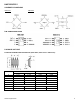
The HMC1501 has an internal sensor die placed toward the forward edge, between pins 1 and 8, to make linear
translation applications more convenient. The figure below indicates this location.
The HMC1512 has two sensor bridges optimized for rotary translation applications. Thus the die is centered in all three
dimensions within the SOIC-8 package. The figure below indicates location.
BASIC DEVICE OPERATION
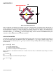
The Honeywell HMC15xx magnetoresistive sensors are Wheatstone bridges to measure magnetic field direction. The
bridge elements change their resistance when a magnetic field is applied across the silicon die with the thin films of
magneto-resistive ferrous material forming the resistive elements. The magnetoresistance is a function of cos2 where
is the angle between the applied magnetic field (M) and the current flow direction in the thin film.
When the applied magnetic field becomes moderate (50 Oerstad or larger), the magnetization of the thin films align in the
same direction as the applied field; and becomes the saturation mode. In this mode, is the angle between the direction
of the applied field and the bridge current flow, and the magnetoresistive sensor is only sensitive to the direction of the
applied field (not amplitude).
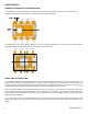
The sensor is in the form of a Wheatstone bridge (see figures below). The resistance (R) of all four bridge legs is the
same. The bridge power supply Vb or Vbridge, causes current to flow through the bridge elements as indicated in the
figures.
0.003”
0.029”
max
0.003”
0.029”
max
GND1 GND2
VO2+ VO1+
VB1
VB2
VO2-
VO1-
GND1 GND2
VO2+ VO1+
VB1
VB2
VO2-
VO1-