
Datasheet


HMC1501/1512
www.honeywell.com 7
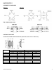
To interface with output pins of the HMC1501 (OUT+, OUT-), an instrumentation amplifier circuit is typically used.
Instrumentation amplifiers can be purchased as complete integrated circuits, or constructed via combinations of discrete
components and integrated circuits; such as operational amplifiers (op-amps). The purpose of an instrumentation amplifier
is to derive the difference signal (OUT+ minus OUT-), and to provide additional signal amplification as desired. The figure
below shows a typical instrumentation amplifier circuit using an op-amp with external discrete components.
With a typical HMC1501 position sensor, a low cost operational amplifier (e.g. LMV358) could be used as a differential
amplifier shown in the schematic above. The 10 kilo-ohm input resistors present a high impedance from the Wheatstone
bridge, and the 249 kilo-ohm resistor set the amplifier gain and bias at 25V/V and 2.5 volts respectively. The 0.01
microfarad capacitor is placed in the feedback loop to low system bandwidth and to further exclude noise outside the
sensor and amplifier circuits. The analog output voltage of the amplifier is typically fed to an Analog-to-Digital Converter
(ADC) stage stand-alone or within a microprocessor integrated circuit. A recommendation of 10-bit ADC circuits or higher
is expected.
For angular measurements, the same information applies, except the mechanical arrangement changes a bit.
Microprocessor
With ADC
HMC1501
U1
+2.5V
10.0k
10.0k
249k
249k
Op-Amp
.01 f
U2
+5.0V
+
-
Analog
output
OUT+
OUT-
Vbridge
Gnd2
Gnd1
ADC0