HMLCD15 15-inch LCD Monitor User Manual Video Systems www.honeywellvideo.com 1-800-796-CCTV © 2004 Honeywell International Inc. All rights reserved. No part of this publication may be reproduced by any means without written permission from Honeywell Video Systems. The information in this publication is believed to be accurate in all respects. However, Honeywell Video Systems cannot assume responsibility for any consequences resulting from the use thereof.
ISSUE DATE A April 2004 SECTION 5: SPECIFICATIONS REVISIONS Initial Release (PCN 1630) LCD PC Input Sync Display Type TFT Color XGA Screen Size 15” (diagonal) Signal RGB Analog Type 15-Pin D-Sub H-Freq 31.5~60KHz V-Freq 56-75Hz Color 16,777,216 Resolution 1024 × 768 (75Hz) OSD Controls Auto Geometry, Auto Brightness, Contrast, H/V Position, etc. Power Management VESA DPMS Power Consumption 30W (max) Power Saving Mode Under 1W Plug & Play DDC1/2B Speaker 2W × 2Ea.
4.4 LIMITED WARRANTY FCC COMPLIANCE STATEMENT Honeywell International Inc. ("Seller"), 1305 Waters Ridge Drive, Lewisville, TX 75057, warrants this monitor to be in conformance with its own plans and specifications and to be free from defects in materials and workmanship under normal use and service for a period of up to one (1) year from the date of manufacture.
SECTION 4: TROUBLESHOOTING AND MAINTENANCE EXPLANATION OF GRAPHICAL SYMBOLS The lightning flash with arrowhead symbol within an equilateral triangle is intended to alert the user to the presence of uninsulated "dangerous voltage" within the product's enclosure that may be of sufficient magnitude to constitute a risk of electric shock to persons. 4.
NOTES: WARNINGS Installation and servicing should be performed only by qualified and experienced personnel. TO PREVENT FIRE OR SHOCK HAZARD, DO NOT EXPOSE THIS PRODUCT TO RAIN OR MOISTURE. SAFEGUARDS This product is made with consideration of the maximum safety of users. However, in order to prevent all possible accidents and financial lost, the monitor must be installed in the appropriate environment. Read instructions and follow all safeguards. POWER WARNINGS 1.
SAFEGUARDS, CONTINUED 2. Rev. A 3.4 Do not place candlelight, mosquito coils, or cigarettes on top of the monitor or install it close to heating appliances. Doing so may damage the product or create a fire danger. The product should be situated away from heat sources such as radiators, heat registers, stoves, or other products (including amplifiers) that produce heat. 3. Do not place this product on an unstable cart, stand, tripod, bracket, or table.
3.3 ON-SCREEN DISPLAY (OSD) CONTROL PROCEDURE, CONTINUED SAFEGUARDS, CONTINUED CLEANING AND GENERAL USAGE Using HOTKEY Frequent adjustments such as auto-geometry, Brightness, Contrast, Audio-volume, Audio-Mute, and Source (selected in RGB/VIDEO) can be quickly done without calling the MENU. The following table describes the HOTKEY. 1 Rev.
3.3 PURCHASE INFORMATION ON-SCREEN DISPLAY (OSD) CONTROL PROCEDURE, CONTINUED Date Purchased: OSD Menu OSD Serial Number: Location Installed: Description Horizontal Position Select OSD Menu horizontal position. Vertical position Select OSD MENU vertical position. Timeout Time after which OSD MENU leaves screen. Transparency Adjust the transparency of the OSD Menu. Language English French German Select one of the five languages.
3.3 ON-SCREEN DISPLAY (OSD) CONTROL PROCEDURE, CONTINUED SECTION 1: INTRODUCTION ............................................................... 1 OSD Menu Description The following table describes the OSD menu and a description of each option. OSD Menu Picture Color TABLE OF CONTENTS Description Auto adjustment Automatically adjusts the Horizontal position, Vertical position, horizontal size and Phase.
TABLE OF CONTENTS, CONTINUED 3.3 ON-SCREEN DISPLAY (OSD) CONTROL PROCEDURE, CONTINUED SECTION 4: TROUBLESHOOTING AND MAINTENANCE................. 19 4.1 TROUBLESHOOTING ................................................................ 19 No Power.................................................................................. 19 Poor Picture Quality.................................................................. 19 4.2 MAINTENANCE......................................................................
3.2 SECTION 1: INTRODUCTION PRESET MODE CHART, CONTINUED The monitor is compatible with additional modes within one of the following specified frequency ranges, provided they are different at least for one of the following: 1.1 Honeywell's HMLCD15 TFT Color LCD Display features a 15.0" viewable active matrix LCD screen, with outstanding 1024 x 768 pixel resolution. When used in PC based applications the HMLCD15 provides connection points for VGA, PC Sound, and headphones.
1.3 3.2 TFT LCD PANEL Black spots (pixels that do not light) or luminescent spots (pixels that are always lit) may appear on the screen because of the intrinsic characteristics of TFT LCD technology. This is neither a malfunction nor a defect in the monitor. The warranty period for the occurrence of black spots and luminescent spots is 1 month from the date of purchase. Monitors with less than 3 such pixels will not be exchanged. The HMLCD15 uses high-voltage fluorescent tubes.
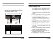
3.2 PRESET MODE CHART 1.4 CONTENTS OF PACKAGE 1. LCD Monitor Timing Charts The monitor shall be capable of supporting the following video timings: VIDEO 2. User Manual 3. VGA Cable USER MANU AL (T4) Active SYNC (T3) Back Poach (T5) Front Poach Synch Width (T2) 4. Sound Cable (T1) Period 5. AC/DC Adapter 6. Installation Disk Input Timing Limits H-Sync Pulse Width 1.0 µs ≤ Sync Pulse Width ≤ 6.0 µs. V-Sync Pulse Width 0.04ms ≤ Sync Pulse Width ≤ 0.5ms 7. Power Cord 8. Video Sound Cable 9.
SECTION 3: OPERATION NOTES: 3.1 POWER MANAGEMENT This monitor is equipped with DPMS (Display Power Management Signaling) function which automatically switches to power saving mode (less than 5 watts consumed) when the computer is left unattended. Although the monitor can be left in power saving mode for longer periods, it is recommended that you turn it off after your daily work. The DPMS function requires support from the computer system of any software DPMS function currently being used.
NOTES: SECTION 2: CONTROLS AND CONNECTIONS 2.1 CONTROLS – FRONT PANEL A B C D E F G Rev. A 8 HMMU000880 04/08/04 Rev.
2.2 CONTROLS – REAR PANEL A B C 2.3 D E F INSTALLING THE MONITOR DRIVER You can achieve an optimal resolution and scanning rate by installing the monitor driver as follows: G 1. Insert the monitor driver diskette into the floppy diskette drive and run INSTALL.EXE. 2. Select the monitor model then press OK. The installation will begin immediately. 2.4 DVR or VCR PC Rev. A VGA CABLE A 15-pin D-Sub connector is used as the input signal connector. Pin and input signal are shown in the table below.