EGPWS LINE MAINTENANCE MANUAL MK V MK VI MK VII MK VIII MK XXII Enhanced Ground Proximity Warning Systems Line Maintenance Manual Document No: 060-4199-180, Rev G Release date: 29 Mar 2010 Honeywell International, Inc. Redmond, Washington 98073-9701 CAGE CODE: 97896 SCALE: NONE SIZE: A DWG NO.
EGPWS LINE MAINTENANCE MANUAL This document is an unpublished work. Copyright 2005, 2010 Honeywell International, Inc. All rights reserved. This document and all information and expression contained herein are the property of Honeywell and is provided to the recipient in confidence on a “need to know” basis. Your use of this document is strictly limited to a legitimate business purpose requiring the information contained therein. Your use of this document constitutes acceptance of these terms.
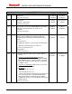
EGPWS LINE MAINTENANCE MANUAL SHT REV All All REVISIONS DESCRIPTION A DATE APPROVED Initial release. 23 FEB 00 R. Halbert Reason 01 Severity 10 23 FEB 00 G. Gilliland Direct update: 07 AUG 01 R. Henderson Incorporate –008 changes 07 AUG 01 L. Matter 13 FEB 02 B. Breen 13 FEB 02 G. Gilliland 08 JAN 04 J. Castro 09 JAN 04 L. Matter 27 SEP 04 K. Christofferson 30 SEP 04 S.
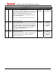
EGPWS LINE MAINTENANCE MANUAL SHT REV All E REVISIONS DESCRIPTION Section 3.3.2 – added RAAS maintenance message to short Level 1 Self-Test sequence and two notes, one to ensure RAAS messages only occur if RAAS is activated and one to explain the GPS NOT NAVIGATING enunciation. DATE APPROVED 01 FEB 05 S. Wright 03 FEB 05 K. Christofferson 23 JUN 09 J. Mulkins Section 3.5 - added note to ensure RAAS message only occurs if RAAS is activated. Section 6.1.
EGPWS LINE MAINTENANCE MANUAL TABLE OF CONTENTS 1 INTRODUCTION..................................................................................................................................................... 8 1.1 SCOPE ...................................................................................................................................................................... 8 1.2 APPLICABILITY ..................................................................................................
EGPWS LINE MAINTENANCE MANUAL 3.8.3 +28V Landing Gear Discrete ..................................................................................................................... 38 3.8.4 GND Landing Flap Discrete or Flap Override ........................................................................................... 39 3.8.5 +28V Landing Flap or Flap Override Discrete........................................................................................... 39 3.8.6 Flap Position Discretes...........
EGPWS LINE MAINTENANCE MANUAL 5.1 GENERAL ................................................................................................................................................................ 57 6 REMOVAL/INSTALLATION................................................................................................................................. 57 6.1 EGPWC............................................................................................................................................
EGPWS LINE MAINTENANCE MANUAL 1 INTRODUCTION 1.1 SCOPE This document provides information about the Enhanced Ground Proximity Warning System (EGPWS) with respect to Line Maintenance Operations. This includes Description and Operation, Troubleshooting, Removal and Installation, Adjustment and Test, and other related information. It is intended that the information in this document be combined with detailed aircraft installation documentation for operator specific line maintenance procedures. 1.
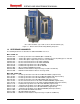
EGPWS LINE MAINTENANCE MANUAL MK V & MK VII EGPWC (left) and MK VI, MK VIII, MK XXII EGPWC (right) Figure 1-1 - Enhanced Ground Proximity Warning Computers 1.3 REFERENCE DOCUMENTS The following documents are identified as additional EGPWS references: MK V and MK VII: 965-0976-603 .........
EGPWS LINE MAINTENANCE MANUAL 2 DESCRIPTION AND OPERATION 2.1 GENERAL SYSTEM DESCRIPTION The purpose for the Enhanced Ground Proximity Warning System (EGPWS) is to help prevent accidents caused by Controlled Flight Into Terrain (CFIT), obstacles, or severe windshear.
EGPWS LINE MAINTENANCE MANUAL 2.1.1 ENHANCED GROUND PROXIMITY WARNING COMPUTER (EGPWC) All EGPWS functions are processed by a single Line Replaceable Unit (LRU) called the Enhanced Ground Proximity Warning Computer (EGPWC). The MK V and MK VII EGPWC are digitally controlled computers housed in a 2 MCU ARINC 600-6 form factor chassis intended for Air Transport type aircraft. Installation configuration is defined by program pin strapping in the aircraft.
EGPWS LINE MAINTENANCE MANUAL provides “TOO LOW TERRAIN” or “TOO LOW FLAPS” depending on airspeed. Mode 4C provides “TOO LOW TERRAIN”. EGPWS alert lights are illuminated during these alerts. 2.2.5 MODE 5 - DESCENT BELOW GLIDESLOPE Mode 5 provides audio and visual alerts for excessive glideslope deviation when the aircraft descends below the glideslope beam on front-course ILS approaches. Two levels of alerting are provided. If the aircraft is below 1000 feet AGL and gets to or exceeds 1.
EGPWS LINE MAINTENANCE MANUAL CALLOUT DESCRIPTION V VI MODEL VII VIII XXII 500 TONE Provides 2 second 960 Hz tone at descent below 500 feet • # • # # SMART “FIVE HUNDRED” At descent below 500 feet (only) during non-precision approach • • • • • “FIVE HUNDRED” Above field callout within 5 nm of a runway in the database # • # • # “FIVE HUNDRED ABOVE” Above field callout within 5 nm of a runway in the database # • # • # “FOUR HUNDRED” At descent below 400 feet • • • • #
EGPWS LINE MAINTENANCE MANUAL 2.2.6.1 EXCESSIVE BANK ANGLE CALLOUT The Bank Angle Callout feature provides callout enunciation for excessive bank angles based on altitude and bank angle limits defined by aircraft type. It is intended to enhance situational awareness during intentional or unintentional maneuvering, and for protection against wing or engine strikes when close to the runway. When the bank angle limit is reached, the aural callout “BANK ANGLE, BANK ANGLE” is given.
EGPWS LINE MAINTENANCE MANUAL When an aircraft penetrates either the TCF or the RFCF alert envelope, the aural message “TOO LOW TERRAIN” will occur. This aural message will occur once when initial envelope penetration occurs, and one time thereafter for each 20% degradation in either Altitude (AGL) or Altitude (ASL) depending on which envelope was violated (TCF or RFCF respectively). EGPWS cockpit alert annunciations remain illuminated until the alert envelope is exited.
EGPWS LINE MAINTENANCE MANUAL The Obstacle Database (in MK V and MK VII -204-204 and later, and MK VI, MK VIII and MK XXII) is a separate file included within the terrain database. Both files are loaded into the EGPWS in the terrain database PCMCIA card. The obstacle database is accessed by the EGPWC application software only if obstacle alerting is enabled by installation configuration.
EGPWS LINE MAINTENANCE MANUAL below the antenna beam scan resulting in a blank display. Alternately, under-scan, where the antennas scan is hitting the ground below the weather cells, results in ground clutter display. The calculated tilt angle is transmitted on the ARINC 429-output bus (labels 061, 062, 063, 064, and 065) for any compatible Weather Radar system. See the appropriate Part Number ICD for complete Label definitions. 2.2.
EGPWS LINE MAINTENANCE MANUAL installation does require that the EGPWS has a source of GPS data, software -230-230 or later, Terrain Database version 454 or later, and the Reloadable Customer Definitions (RCD) is loaded. When enabled, Altimeter Monitor operates automatically, without any action required from the flight crew. Altimeter Monitor availability can be verified by performing an EGPWS self test. See Appendix E for Altimeter Monitor Maintenance Messages. 2.2.
EGPWS LINE MAINTENANCE MANUAL 2.2.21 LAMP FORMAT The EGPWS contains two different caution/warning lamp illumination formats as described below. Lamp Format 1 provides EGPWS warning (red) and caution (amber) alert lamp drive logic such that: • Only a Mode 5 “Glideslope” alert will activate the caution lamp output (amber). • All other alerts (except “windshear” and Mode 6 callouts) will activate the warning lamp output (red).
EGPWS LINE MAINTENANCE MANUAL 2.3 SYSTEM MAINTENANCE 2.3.1 MAINTENANCE PHILOSOPHY The EGPWS is an “on-condition” only maintenance system. No scheduled maintenance is required. This is accomplished by both continuous Built-In-Test (BIT) and event initiated test functions. Event initiated test refers to both power-up tests and manually activated Self-Tests. Results of these functions are indicated by system status indicators and messages so that the systems functionality can be assessed.
EGPWS LINE MAINTENANCE MANUAL These tests primarily consist of more thorough hardware checks that would disrupt normal operation if continuously run. 2.3.4 EGPWC FRONT PANEL To aid in troubleshooting the EGPWS, the front panel of the Warning Computer provides indicators and user interfaces as follows. 2.3.4.1 EGPWS STATUS LED’S Three LED’s on the EGPWC front panel provide a high level indication of overall system status.
EGPWS LINE MAINTENANCE MANUAL 2.3.5 SELF-TEST FUNCTIONS The EGPWC supports a manually operated Self-Test sequence for indicating the operational status of the system. The Self-Test aurally enunciates the EGPWS status and activates outputs (lights and displays) for visual verification.
EGPWS LINE MAINTENANCE MANUAL 3 FAULT ISOLATION (TROUBLESHOOTING) 3.1 GENERAL The troubleshooting methods provided in this section identify system and sensor or subsystem faults to the lowest level possible. Additional fault isolation in the installation or associated sensors or subsystem should be performed using the aircraft installation and wiring diagrams and other supporting documentation in accordance with established maintenance procedures.
EGPWS LINE MAINTENANCE MANUAL 3.3 LEVEL 1 SELF-TEST - GO/NO GO TEST Level 1 Self-Test provides an overview of the current operational capability of the EGPWS. It is divided into 3 functions - the Preamble, Short Level 1 Self-Test, and Long Level 1 Self-Test as described in the following sections. During Level 1 Self-Test, a Short Cancel terminates the Self-Test level and “CURRENT FAULTS” is enunciated to indicate activation of Level 2 Self-Test.
EGPWS LINE MAINTENANCE MANUAL POSSIBLE SELF-TEST PREAMBLE RESULTS Enunciation: Probable Cause: Action: “CONFIGURATION MODULE NOT PROGRAMMED” (MK VI, MK VIII, MK XXII only) The Configuration Module is not programmed. Program the Configuration Module. See Maintenance Practices section. Enunciation: Probable Cause: “CONFIGURATION MODULE NOT COMPATIBLE” (MK VI, MK VIII, MK XXII only) The Configuration Module is not compatible with the EGPWC h/w or s/w or it’s faulty. Verify Configuration Module connections.
EGPWS LINE MAINTENANCE MANUAL Installations that do not have the windshear function or the function enabled will not enunciate the windshear message and illuminate windshear alert lights. Similarly, installations without the Terrain Alerting and Display (TAD) function enabled will not have terrain lights and display or “TERRAIN” aural enunciation. • NOTE: The general sequence of the LEVEL 1 SELF-TEST is the same for all installations.
EGPWS LINE MAINTENANCE MANUAL 3.4.1 CURRENT FAULTS - INTERNAL An internal fault indicates a problem with the EGPWC. The following table lists the internal fault messages and the probable maintenance response. Note: “NO FAULTS” is enunciated for Level 2 Self-Test if no faults are present.
EGPWS LINE MAINTENANCE MANUAL TABLE 3-3: CURRENT FAULTS - EXTERNAL (EXAMPLES) FAULT ARINC 429 Bus Fault EXAMPLE GPS BUS 1 INACTIVE ARINC 429 Signal Fault ILS BUS 1 GLIDESLOPE FAULT FW ARINC 429 Signal Fault ILS BUS 1 GLIDESLOPE FAULT UPD Analog Signal Fault RADIO ALTIMETER 1 WIRING FAULT AOA UNREASONABLE FAULT Discrete Input Faults FLAP SWITCH FAULT GEAR SWITCH FAULT AUDIO CANCEL INVALID TERRAIN INHIBIT INVALID GPWS INHIBIT INVALID ALL MODES INHIBIT INVALID GLIDESLOPE CANCEL INVALID ILS SELECT
EGPWS LINE MAINTENANCE MANUAL TABLE 3-4: LEVEL 2 SELF-TEST - EXTERNAL FAULTS THE FOLLOWING EXTERNAL FAULTS ARE AVAILABLE IN LEVEL 2 SELF-TEST: Enunciation: “ Inactive” Example: GPS BUS 1 Inactive Probable Cause: Input source not powered or a wiring problem exists between source LRU and the EGPWC. Action: Verify input source LRU is powered. Verify wiring from the source LRU. Verify program pin configuration.
EGPWS LINE MAINTENANCE MANUAL THE FOLLOWING EXTERNAL FAULTS ARE AVAILABLE IN LEVEL 2 SELF-TEST: Description: SELF-TEST INVALID (WinVIEWS ONLY) Probable Cause: Electrical short at the Self-Test input. Action: Verify wiring from the Self-Test discrete. Enunciation: “MOMENTARY TERRAIN SELECT 1 (or 2) INVALID” Probable Cause: Electrical short at the Terrain Select inputs. Action: Verify wiring from the terrain “ON” switches.
EGPWS LINE MAINTENANCE MANUAL TABLE 3-5: GENERAL FAILURE CODE IDENTIFIERS For example, if the Computed Airspeed from Air Data Computer #1 is failed (i.e., SSM = Fail Warning), the following messages would be enunciated: “CURRENT FAULTS” “EGPWC OK” “EXTERNAL FAULTS” “AIR DATA BUS 1 COMPUTED AIRSPEED FAULT” “PRESS TO CONTINUE” CAGE CODE: 97896 SCALE: NONE SIZE: A DWG NO.
EGPWS LINE MAINTENANCE MANUAL NOTE: Before attempting to correct an external fault, verify that the EGPWS installation configuration matches the aircraft configuration. If the installation configuration and aircraft configuration does not match, check the Program Pin or Configuration Module connections being sure to cycle power to the EGPWC in the process.
EGPWS LINE MAINTENANCE MANUAL 3.5 LEVEL 3 SELF-TEST - SYSTEM CONFIGURATION A Level 3 Self-Test enunciates EGPWC configuration information. Level 3 is accessed while the aircraft is on the ground by pressing the EGPWS test switch within 3 seconds of the “PRESS TO CONTINUE” message at the end of the Level 2 test. The message “SYSTEM CONFIGURATION” will be enunciated when Level 3 starts. During a Level 3 Self-Test, a short cancel bumps the enunciation to the next Level 3 item (e.g.
EGPWS LINE MAINTENANCE MANUAL THE FOLLOWING INFORMATION IS GIVEN IN THE LEVEL 3 SELF-TEST: “IRS 1 ATTITUDE MODE SELECTED” “ MODE 6 INOP-NO Decision Height” (approaching minimums in menu).
EGPWS LINE MAINTENANCE MANUAL THE FOLLOWING INFORMATION IS GIVEN IN THE LEVEL 3 SELF-TEST: “GPS ALTITUDE REF WGS84 SELECTED” “AUTOROTATION CALLOUT X SELECTED” (MK XXII) “NORMAL POPUP RANGE X SELECTED” (MK XXII) “LOW ALTITUDE POPUP RANGE X SELECTED” (MK XXII) “MODE 6B ALWAYS ON SELECTED” (MK XXII) “NORMAL TERRAIN WITH AIRSPEED SELECTED” (MK XXII) “LOW ALTITUDE WITH AIRSPEED SELECTED” (MK XXII) “SAR LOW ALTITUDE SELECTED” (MK XXII) “AUDIO INHIBIT TIME X” (MK XXII) “INHIBIT ALL EXCEPT MINIMUMS TYPE CALLOUT AND
EGPWS LINE MAINTENANCE MANUAL 3.6 LEVEL 4 SELF-TEST - FAULT HISTORY Level 4 Self-Test provides enunciation of the faults recorded over the last 10 flight legs. Level 4 Self-Test is initiated by pressing the cockpit Self-Test button within 3 seconds of the end of Level 3 Self-Test. If any faults were recorded in the last ten flight legs then voice sequence as described in the following table will be enunciated. Otherwise, the message “NO FAULTS” will be enunciated.
EGPWS LINE MAINTENANCE MANUAL 3.7 LEVEL 5 SELF-TEST - ALERT HISTORY Level 5 Self-Test provides enunciation of the alerts (cautions and warnings) recorded over the last 10 flight legs. Level 5 Self-Test is initiated by pressing the cockpit Self-Test button within 3 seconds of the end of Level 4 SelfTest. If any alerts were recorded in the last ten flight legs then voice sequence as described in the following table will be enunciated. Otherwise, the message “NO WARNINGS” will be enunciated.
EGPWS LINE MAINTENANCE MANUAL 3.8.1 ARINC 552 / ALT 55 RADIO ALTITUDE VALIDITY FLAG DISCRETES Three Radio Altitude validity flags may be used by the EGPWS, one for each of the three possible ARINC 552 or ALT 55 Radio Altimeters inputs. Type Validity from ARINC 552 or ALT 55 Radio Altimeter.
EGPWS LINE MAINTENANCE MANUAL 3.8.4 GND LANDING FLAP DISCRETE OR FLAP OVERRIDE Type: Supplied by Flap or Flap selector handle switch. This input can be paralleled with, or used exclusively by a Flap Override Switch if an alternate source of Flap Position is used. Signal Status: Landing Flaps or Not Landing Flaps Fault monitoring: Indication of landing flaps selected for more than 60 seconds at airspeeds above 250 knots will result in a flap switch fault which will cause a GPWS INOP indication.
EGPWS LINE MAINTENANCE MANUAL 3.8.6 FLAP POSITION DISCRETES Up to four flap position discretes are typically supplied from the flap selector handle switch. Type: Supplied by Flap selector handle switch. Signal Status: Flap position selected. Fault monitoring: Depending on the installation, activation of more than one, or none of these discretes for more than 30 seconds will result in a Flap Unreasonable indication.
EGPWS LINE MAINTENANCE MANUAL 3.8.8.2 STEEP APPROACH DISCRETE #2 Type: Steep Approach Selected Signal Status: Steep Approach Selected or Not Selected Steep Approach Discrete #2 Level 6 Audio readout Selected => “Steep Approach Selected” Not Selected => “Steep Approach Not Selected” 3.8.9 GND ILS TUNED DISCRETE Type: Supplied by ILS/VOR Mode Selector.
EGPWS LINE MAINTENANCE MANUAL 3.8.12 GND GLIDESLOPE INHIBIT DISCRETE Type: Switch for inhibit of Glideslope mode Signal Status: Glideslope Inhibit or Not Inhibit Fault monitoring: Mode 5 will be disabled and “Glideslope” will not be enunciated during cockpit Self-Test and the long vocabulary test if inhibited. Level 6 Audio readout Inhibit => “Glideslope Inhibit True” Not Inhibit => “Glideslope Inhibit False” Glideslope Inhibit Discrete 3.8.
EGPWS LINE MAINTENANCE MANUAL 3.8.16 MODE 6 VOLUME CONTROL DISCRETE Type: Mode 6 low volume select switch Signal Status: Low Volume Select or Normal Volume “Low Volume” in this case refers to the -6db volume level used during Self-Test. “Normal Volume” refers to the level of the selected call-out menu. Mode 6 Low Volume Discrete Level 6 Audio readout Low Volume => “Mode 6 Low Volume” Normal => “Mode 6 Normal Volume” 3.8.
EGPWS LINE MAINTENANCE MANUAL 3.8.20 AOA VALIDITY DISCRETES (MK V AND MK VII ONLY) Two AOA validity discretes may be used by EGPWS, one for each source of AOA. Input will come from either an AOA Indication System or a Stall Warning Computer, depending on the type being used by the aircraft.
EGPWS LINE MAINTENANCE MANUAL 3.8.24 WEATHER RADAR ON/OFF Type: WXR On/Off switch input Signal Status: Radar turned on or off Level 6 Audio readout On => “Weather On” Off => “Weather Off” On => “Weather 2 On” Off => “Weather 2 Off” WXR #1 On Discrete WXR #2 On Discrete 3.8.25 LOCALIZER VALIDITY DISCRETES (MK V AND MK VII ONLY) Two Localizer validity discretes may be used by EGPWS, one for each possible ARINC 547 Localizer Receiver input. Type: Validity from ARINC 547 Localizer receiver.
EGPWS LINE MAINTENANCE MANUAL 3.8.28 BAROMETRIC ALTITUDE RATE VALIDITY DISCRETES Two Barometric Altitude Rate validity discretes may be used by EGPWS, one for each possible barometric rate sensor. Type: Validity from barometric rate sensor.
EGPWS LINE MAINTENANCE MANUAL 3.8.33 MAGNETIC HEADING VALIDITY DISCRETE A Magnetic Heading validity discrete may be used by EGPWS for the Magnetic Heading sensor. Type: Validity from Magnetic Heading sensor. Signal Status: Valid or Invalid Level 6 Audio readout Valid => “Magnetic Heading Valid” Invalid => “Magnetic Heading Invalid” Magnetic Heading Validity Discrete 3.8.34 AOA VANE HEATER DISCRETE An AOA Vane Heater Discrete may be used by EGPWS for indication of vane heat for flight history recording.
EGPWS LINE MAINTENANCE MANUAL 3.8.37 TACTICAL SELECT DISCRETE Tactical Select discrete may be used by EGPWS for an indication that the Tactical Select switch has been pressed. Type: momentary make/break switch Signal Status: Tactical Select Selected or Not Selected Level 6 Audio readout Selected => “Tactical Selected” Not Selected => “Tactical Not Selected” Tactical Select Discrete 3.8.
EGPWS LINE MAINTENANCE MANUAL 3.8.41 WEIGHT ON WHEELS DISCRETE Weight On Wheels Discrete may be used by EGPWS to determine if the aircraft is on the ground. Type: Weight On Wheels Status Signal Status: On Ground or Not On Ground Selected => Not Selected => Weight On Wheels Discrete Level 6 Audio readout “On Ground” “Not On Ground” 3.8.42 GPWS INHIBIT DISCRETE This discrete inhibits all audio and visual except for Windshear, Terrain Awareness and TCF.
EGPWS LINE MAINTENANCE MANUAL 3.8.45 STABILIZED APPROACH MONITOR ENABLE DISCRETE (MK V AND MK VII ONLY) Type: Discrete for enabling Stabilized Approach Monitor functionality Signal Status: Approach Monitor Enabled or Disabled True => False => Stabilized Approach Monitor Enable Discrete Level 6 Audio readout “Approach Monitor Enabled” “Approach Monitor Disabled” 3.8.
EGPWS LINE MAINTENANCE MANUAL 4 MAINTENANCE PRACTICES 4.1 GENERAL Normal maintenance activities performed on the EGPWS should follow standard industry maintenance practices. System maintenance practices may include; updating a database, downloading flight history data, and programming or reprogramming the MK VI, MK VIII or MK XXII Configuration Module. These are addressed in the following sections. 4.
EGPWS LINE MAINTENANCE MANUAL The database may be loaded either while the EGPWC is on the aircraft or on a bench provided the appropriate power is applied. Each Honeywell database Service Information Letter includes reference to the procedure for loading the database in the EGPWC. Refer to the SIL for this information. 4.3 FLIGHT HISTORY DOWNLOADING In flight, the EGPWC records detected faults, and data prior to and following an alert.
EGPWS LINE MAINTENANCE MANUAL NOTE: This operation should require no more than 10 minutes. NOTE: If the XFER FAIL LED turns ON instead of the XFER COMP LED, then a different Flight History Download PCMCIA Card must be obtained from Honeywell for the Data Download. 9. Remove the PCMCIA Card, For the MK V or MK VII, depress the PUSH TO EJECT button on the EGPWC front panel. For the MK VI or MK VIII, and MK XXII, carefully grasp the card and pull from the Smart Cable.
EGPWS LINE MAINTENANCE MANUAL 4.4 PROGRAMMING THE CONFIGURATION MODULE (MK VI, MK VIII, MK XXII ONLY) Programming the EGPWS Configuration Module is accomplished using WinVIEWS on a PC connected to the EGPWC via the RS-232 interface. Prior to this activity, the necessary and desired configuration should be determined based on the MK VI, MK VIII, or MK XXII Installation Design Guide referenced in Section 1.3. Utilize a copy of Appendix E, Table 5.
EGPWS LINE MAINTENANCE MANUAL 4.4.1 CONFIGURATION MODULE REPROGRAMMING (MK VI, MK VIII, MK XXII ONLY) Reprogramming the EGPWS Configuration Module is accomplished similar to the programming process above. Prior to reprogramming, the desired new configuration should be determined based on the MK VI, MK VIII, or MK XXII Interface Design Guide (IDG) document referenced in Section 1.3. For reprogramming the Configuration Module, the following procedure is used: 1.
EGPWS LINE MAINTENANCE MANUAL An example CUW command/data string, its definition, and the corresponding CWR list is provided below.
EGPWS LINE MAINTENANCE MANUAL 5 SERVICING 5.1 GENERAL The EGPWS does not require any servicing. 6 REMOVAL/INSTALLATION 6.1 EGPWC 6.1.1 REMOVAL 1. Remove power to the EGPWC. 2. (MK VI, MK VIII, and MK XXII only) Disconnect aircraft connectors from the front of the unit. 3. Turn hold-down counterclockwise and unlatch from EGPWC. 4. Remove EGPWC from aircraft equipment rack. 6.1.2 INSTALLATION 1. Ensure power is off to the EGPWC rack. 2.
EGPWS LINE MAINTENANCE MANUAL 4. Align the Configuration Module housing to the P2 connector ensuring that wires are properly contained within the connector assembly. 5. Install the two screws securing the Configuration Module to the P2 connector. 6. Connect the P2 connector assembly to the EGPWC. 7. Provide power to EGPWC and all required sensors and subsystems. 8. Program the Configuration Module per the instructions in Section 4.4 and any appropriate aircraft drawings that define the proper values to use.
EGPWS LINE MAINTENANCE MANUAL 8 INSPECTION/CHECK 8.1 GENERAL The EGPWS does not require any specific periodic inspection or checks. The system should be inspected for integrity and checked for wear/tear during the course of routine aircraft maintenance inspections. 9 CLEANING/PAINTING 9.1 GENERAL The EGPWS does not contain any elements that required cleaning or painting on the aircraft. Any cleaning or painting of the EGPWC should be performed by an authorized EGPWS repair facility. 10 REPAIRS 10.
EGPWS LINE MAINTENANCE MANUAL 11 APPENDIX A: WINVIEWS WinVIEWS (Windows Virtual Interface to the Enhanced Warning System) is a software tool developed by Honeywell to monitor or view values within the EGPWC, and perform certain test interface functions. Overview: The WinVIEWS software provides a monitor function that does not alter the operation of the EGPWS.
EGPWS LINE MAINTENANCE MANUAL 12 APPENDIX B: TROUBLESHOOTING DO’S AND DO NOT’S DO use built-in self test levels to find the exact nature of the fault.
EGPWS LINE MAINTENANCE MANUAL 13 APPENDIX C: RAAS MAINTENANCE MESSAGES (AURAL & DISPLAYED) TABLE C1-1: RAAS MAINTENANCE MESSAGES MAINT. FUNCTION MESSAGE NOTES: Except where noted, all maintenance message voices are Male All volume levels at same volume as existing EGPWS Self-Test messages “Runway Awareness OK - Feet” RAAS enabled, functioning, has good position information, and is at a validated airport. Distances annunciated in Feet.
EGPWS LINE MAINTENANCE MANUAL TABLE C1-2: RAAS DISPLAYED MAINTENANCE MESSAGES MAINT. FUNCTION DISPLAYED MESSAGE NOTES: RAAS Display messages are displayed OnGround only. To initiate, change the display range. Message displayed only the selected channel. Self-Test Level 1 (Displayed as part of the EGPWS SelfTest Pattern ) On-Ground status RCDxyz12 (magenta)* * May be green depending on display 1 Displayed immediately above or below the TDB Version display.
EGPWS LINE MAINTENANCE MANUAL 14 APPENDIX D: STABILIZED APPROACH MONITOR MAINTENANCE MESSAGES TABLE D-1: STABILIZED APPROACH MONITOR MAINTENANCE MESSAGES MAINT.
EGPWS LINE MAINTENANCE MANUAL 15 APPENDIX E: ALTIMETER MONITOR MAINTENANCE MESSAGES TABLE E-1: ALTIMETER MONITOR MAINTENANCE MESSAGES MAINT.
EGPWS LINE MAINTENANCE MANUAL 16 APPENDIX F: TAKEOFF FLAP CONFIGURATION MONITOR MAINTENANCE MESSAGES TABLE F-1: TAKEOFF FLAP CONFIGURATION MONITOR MAINTENANCE MESSAGES MAINT. FUNCTION MESSAGE NOTES: Except where noted, all maintenance message voices are Male All volume levels at same volume as existing EGPWS Self-Test messages Self-Test Level 1 “Flaps Monitor Inhibited” Takeoff Flap Configuration Monitor enabled, but the advisories have been inhibited with the activation of an external input/switch.
EGPWS LINE MAINTENANCE MANUAL 17 APPENDIX G: LONG LANDING MONITOR MAINTENANCE MESSAGES TABLE G-1: LONG LANDING MONITOR MAINTENANCE MESSAGES MAINT.
EGPWS LINE MAINTENANCE MANUAL 18 APPENDIX H: LOW AIRSPEED MONITOR MAINTENANCE MESSAGES TABLE H-1: LOW AIRSPEED MONITOR MAINTENANCE MESSAGES MAINT. FUNCTION MESSAGE NOTES: Except where noted, all maintenance message voices are Male All volume levels at same volume as existing EGPWS Self-Test messages Self-Test Level 1 ”Airspeed Low” Low Airspeed Monitor enabled, functioning, has all required input information.