HercuLine® 2000 Series Actuator Installation, Operation and Maintenance Manual Honeywell Field Solutions Doc. No.
Notices and Trademarks Copyright 2007 by Honeywell Revision 6 July 2007 Warranty/Remedy Honeywell warrants goods of its manufacture as being free of defective materials and faulty workmanship. Contact your local sales office for warranty information. If warranted goods are returned to Honeywell during the period of coverage, Honeywell will repair or replace without charge those items it finds defective.
About This Document Abstract This manual describes the installation, set up, operation, maintenance, and troubleshooting of the HercuLine 2000 series actuators. References The following list identifies all documents that may be sources of reference for material discussed in this publication.
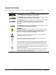
Symbol Definitions The following table lists those symbols that may be used in this document to denote certain conditions. Symbol Definition This DANGER symbol indicates an imminently hazardous situation, which, if not avoided, will result in death or serious injury. This WARNING symbol indicates a potentially hazardous situation, which, if not avoided, could result in death or serious injury. This CAUTION symbol may be present on Control Product instrumentation and literature.
Contents Contents Contents................................................................................................................v Introduction ...........................................................................................................1 Product Description ...................................................................................................................... 1 Model distinctions..........................................................................................
Contents Configuration Prompt Hierarchy ................................................................................................. 38 Input Set Up Group..................................................................................................................... 39 Equal Percentage Valve Characteristic ..................................................................................................42 Quick Opening Valve Characteristic..........................................................
Contents Upgrade Kits............................................................................................................................. 102 Accessory Kits .......................................................................................................................... 104 Troubleshooting ................................................................................................105 Introduction.........................................................................................
Contents Tables Table 1 Specifications - General.................................................................................................................................. 5 Table 2 Recommended Minimum Wire Size............................................................................................................. 17 Table 3 Terminal Connections: HercuLine® 2000....................................................................................................
Contents Figures Figure 1 HercuLine® 2000 Series Actuator ................................................................................................................. 2 Figure 2 HercuLine® 2002 Actuator Internal View ..................................................................................................... 3 Figure 3 Outline and Dimensions of HercuLine® 2000 Series Actuators................................................................. 14 Figure 4 Constant Torque Linkage ................
Introduction Product Description Introduction Product Description Honeywell’s HercuLine® 2000 series actuators are available in four versions: HercuLine® 2000, HercuLine® 2001, HercuLine® 2002, and HercuLine® 2003. All are low torque, precision electric rotary actuators incorporating all of the high quality and reliable features of the traditional HercuLine series actuators.
Introduction Product Description Display and keypad Handwheel Conduit entry Shaft and position indicator Auto/manual switch Figure 1 HercuLine® 2000 Series Actuator 2 HercuLine™ 2000 Series Actuator - Installation, Operation and Maintenance Manual Revision 6 7/07
Introduction Product Description Display Keypad PWA Wiring Label Mechanical Stops TB3 Connector for customer input and output connection on CPU PWA Cams and limit switches TB1 customer power connection Relay PWAs Non-contact sensor External auto-manual switch Figure 2 HercuLine® 2002 Actuator Internal View Revision 6 7/07 HercuLine™ 2000 Series Actuator - Installation, Operation and Maintenance Manual 3
Introduction Product Description 4 HercuLine™ 2000 Series Actuator - Installation, Operation and Maintenance Manual Revision 6 7/07
Specifications Technical and Operating Specifications Specifications This section provides you with the technical specifications and the model selection guide for the HercuLine® 2000 Series Actuators. Technical and Operating Specifications Table 1 Specifications - General Physical Weight 2000: 25 lb. (11.36 kg) 2001,2002: 27 lbs. (12.27 kg) Enclosure Precision-machined die cast aluminum housing, finished in light gray powder coat epoxy.
Specifications Technical and Operating Specifications Electrical Mains Supply 100-130 Vac single phase, 50 Hz or 60 Hz 200-240 Vac single phase, 50 Hz or 60 Hz Motor Instant start/stop, non-coasting, non-burnout, continuous duty, permanent magnet, synchronous induction motor. Can be stalled up to 100 hours without damage. Motor Current = No load = full load = locked rotor = 0.4 amp for 120Vac, 0.
Specifications Technical and Operating Specifications HercuLine® 2002 HercuLine® 2001 HercuLine® 2000/2003 Feedback Slidewire emulation - Provides output voltage ratiometric to shaft position and potentiometric to supply voltage (1 Vdc to 18 Vdc) without a slidewire. Emulates a 100 ohm to 1000 ohm slidewire. 10 mA output maximum.
Specifications Technical and Operating Specifications HercuLine® 2002 HercuLine® 2001 Selectable and configurable operating parameters: Programmable Functions HercuLine® 2000/2003 NA • Input range • Input filtering • Input characterization • Security • Digital Input action • Deadband • Failsafe on loss of input signal • Failsafe on loss of position sensor • Direction of rotation • Relay closure action • Communication parameters • Split range operation • Output range • Alarms Specifications – Local Di
Specifications Technical and Operating Specifications Specifications – Communications Communications Communications Option RS 485 Serial Communication, Modbus RTU Protocol Connection Twisted pair cable with shield Maximum loop length 600 meters (2000 feet) Communication Mode Half duplex Baud Rate 300, 600, 1200, 2400, 4800, 9600, 19.2K Required Specifications – PDA (customer provided) PDA Operating System Palm OS version 3.
Specifications Model Selection Guide Model Selection Guide Instructions Select the desired key number. The arrow to the right marks the selection available. Make the desired selections from Tables I thru VIII using the column below the arrow. A dot ( ) denotes unrestricted availability.
Specifications Model Selection Guide 2000 2001 2002 2003 TABLE VI - OPTIONS Local keypad/ display Local Auto/ manual switch Handwheel Certificates Approvals Shipped Rotation No local display interface supplied (Note 2) Integrally mounted local display/keypad interface No auto/manual switch Auto/manual switch with "Out of Auto Contact" Auto/manual switch with "Out of Auto Contact" No Handwheel Handwheel None Certificate of Conformance UL Type 4/IP66, CSA (Note 4) CE Counter clockwise shaft rotation on in
Installation Installation Overview Installation Installation Overview The procedures to install the HercuLine® 2000 Series actuator and place it in service require that you: • Select a suitable location for installation. (See Installation Considerations below.) • Mount the actuator securely. • Install mechanical connections or linkage between control arm and final control element. Use HAL software application to aid in mechanical installation.
Installation Before Starting Before Starting Unpacking If there are visible signs of damage to the shipping container, notify the carrier and Honeywell immediately. If there is no visible damage, compare the contents with the packing list. Notify the carrier and Honeywell immediately if there is equipment damage or shortage. Please do not return goods without contacting Honeywell Applications Center in advance. The contact number is 1-800-423-9883.
Installation Actuator Mounting CLEARANCE FOR TOP REMOVAL: 101,6 4.0 289 11.379 25.4 1.
Installation Mechanical Installation Mechanical Installation Linkage Set-up Many applications require the use of a linkage assembly and often the final control element does not have a linear torque curve. The actuator linkage can be set up to achieve an optimal delivered torque distribution for specific applications. To assist with linkage design, Honeywell offers a linkage analysis software application (HAL). The software can be ordered as P/N 51197910-001.
Installation Mechanical Installation Vertical Centerline Vertical Centerline 45° Actuator Crank Arm 45° Linkage Close 5° Horizontal Offset a/n 23200 Open Damper Crank Arm Figure 5 Variable Torque Linkage Actuator Crank Arms The HercuLine® 2000 Series Actuator comes standard with a crank arm with adjustable radius of 1.0 in (25.4mm) to 2.80 in (71.12mm). See Figure 6.
Installation Electrical Installation Electrical Installation General Wiring Recommendations Only qualified personnel should perform wiring. Wiring must conform to national and local electrical codes. In general, copper wire used. Unless locally applicable codes dictate otherwise, the recommended minimum wire sizes in Table 2 should be observed. Table 2 Recommended Minimum Wire Size AWG Description 14 Earth ground wire to common power supply. 18 Earth ground wire to single actuator.
Installation Electrical Installation HercuLine® 2000 Terminal Connections Table 3 Terminal Connections: HercuLine® 2000 Connection Descriptions Terminal Numbers and LABEL See Figure 8 Hot 1 Hot wire for 120/240VAC mains supply. Use only if Auto/Manual switch is present. Neutral 2 Neutral wire for 120/240VAC mains supply Auto/Manual Switch Contact 3 4 Switch contact to indicate setting of actuator AUTO/MANUAL switch.
Installation Electrical Installation HercuLine® 2001/2002 with Auto/Manual Terminal Connections Table 4 Terminal Connections: HercuLine® 2001/2002 with auto/manual Terminal Numbers and LABEL Connection Descriptions See Figure 9 TB1 Hot 1 Hot wire for 120/240VAC mains supply Neutral 2 Neutral wire for 120/240VAC mains supply Protective Ground 3 Ground wire connection for mains supply Auto/Manual Switch Contact 4 5 Switch contact to indicate setting of actuator AUTO/MANUAL switch.
Installation Electrical Installation HercuLine® 2003 Wiring Connections and Operation (Actionator 640D Replacement) Wiring Figure 10 HercuLine® 2003 connections Operation The 2003 actuator is uni-directional (it does not reverse rotation with a reversal in control action). Figure 10 illustrates the internal wiring and the external connections. The smaller insert of the figure describes the limit switch action for one complete cycle.
Installation Electrical Installation Power Connections Depending on which power supply selection is ordered for your actuator, wire the power input (MAINS POWER) as described in the previous tables and figures. Wiring must conform to national and local electrical codes. CE Wiring When wiring the actuator power input for CE approved units, you must also install a MOV and ferrite beads supplied with the CE unit.
Installation Electrical Installation Step 8 Action • AC power connection • Auxiliary switches connection • Relay contact connection Aux switches 1 and 2 (SW3 and SW4) Aux switches 3 and 4 (SW5 and SW6) Relays 1 and 2 Relays 3 and 4 AC power connection Figure 12 CE Wiring part 2 9 Install new gasket and top cover. Secure top cover with 6 captive screws. 10 Reapply AC power to the actuator. 11 Actuator is ready for use.
Burner Control/Flame Safety Electrical Installation Output Signal Connections 0/4-20 mA, 0/1-5 Vdc Feedback Signal Connections ATTENTION Shielded and grounded cables are recommended. Actuator output is a 4 to 20 mA analog signal. If a voltage input is required for customer devices, a range resistor is needed at the device input. Refer to (page 19) for more information. Slidewire Emulator Connections ATTENTION Shielded and grounded cables are recommended.
Burner Control/Flame Safety Series 90 Control – HercuLine® 2001 model only Series 90 Control – HercuLine® 2001 model only Series 90 Controls are commonly used in building environmental systems and flame safeguard systems to provide modulating control. The control is affected by balancing a 135 ohm potentiometer. The HercuLine 2001 provides an emulation of this system as follows. The current output is used to excite the potentiometer in the controller. To do this it is set permanently at 11 ma.
Burner Control/Flame Safety Series 90 Control – HercuLine® 2001 model only Auto I out from HercuLine2001 W W T775 B 3 W + Signal to HercuLine2001 T775 W 1 R R Man GND to HercuLine2001 (2) B B T775 R 2 Figure 15 T775 Controller connections 3. Revision 6 7/07 In the T775 controller manual there are several examples of using resistances or potentiometers as high and low limit controls. Because of the mode of emulation of Series 90, it is likely that these connections will not work as intended.
Burner Control/Flame Safety Split Range Split Range The HercuLine® 2001/2002 actuators can be set up to operate within a narrow input range (for example, 4 to 12mA input) in certain applications. The procedure in Table 5 describes how to set up an actuator to operate as part of a split valve configuration. Table 5 Split Range Set Up Procedure Step Action To Set Actuator span to operate from 4 to 12 mA input.
Burner Control/Flame Safety Master/Slave Arrangement Basic Flow Control When the process variable signal is below set point, the controller increases current (4 to 20mA) to the actuator input and opens the valve. Controller set point governs valve position to obtain desired flow rate.
Burner Control/Flame Safety Master/Slave Arrangement Orifice Plate PV FT Positioner & Actuator Controller SP 4 to 20 mA FIC MP #1 Valve Linkage MP #2 Linkage Valve Proportional with Bias MP #3 Linkage Valve Ratio Position mA Figure 18 Proportional Flow Using Multiple Actuators Current Output Controller + 4 to 20 mA Note: Controller must be capable of sourcing the impedance.
Burner Control/Flame Safety Master/Slave Arrangement Current Output Controller 10260S Actuator Series Actuator #1 #1 Jumper W2 + 4 to 20 mA - = Current 250 Ohms 1 to 5 VDC Hot Neutral Ground 120/240 VAC 10260S Series Actuator #2 Actuator #2 See Figure 27 for jumper location Jumper W2 = Voltage Hot Neutral 120/240 VAC Ground 10260S Series Actuator #3 Actuator #3 Alternate Wiring Jumper W2 = Voltage Hot Neutral 120/240 VAC Ground Figure 19 Multiple Actuator Interconnection Diagrams NOTE: If
Burner Control/Flame Safety Master/Slave Arrangement Split Valve Configuration A common heat or cool type process requires two valves. In this case the controller has only one output. The two motor positioners are calibrated differently, one responds to 4 to 12mA and the other responds to 12 to 20mA. At 12mA, both valves are closed; one opening below 12mA and the other above 12mA. Refer to Figure 20 for an interconnection diagram for split valve operation using two actuators.
Set Up and Calibration Procedures Overview Set Up and Calibration Procedures Overview Once you have installed the actuator, you can verify, set or change certain operating parameters. Set up is accomplished through use of the local display and keypad interface through your PDA with HercuLink® software (see HercuLink® manual 62-86-25-11) or via the HART® communication option.
Set Up and Calibration Procedures Local Display and Keypad Table 6 Keypad Description Key or LED Indicator Function SET UP Places the actuator in the set up group select mode. Sequentially displays the set up groups and allows the FUNCTION key to display function parameters within the set up group. See Set Up and Calibration Procedures (page 31)Error! Reference source not found. for descriptions of the various options available in the set up groups.
Set Up and Calibration Procedures Set Up Tips Set Up Tips Table 7 contains tips that will help you view, verify and enter the operating parameters more quickly. If you cannot change the parameters, check the status of the “SET LOCK” parameter. Also some parameters require that you enter a security password before you access or change the parameter value. Table 7 Set Up Tips Function Tip Displaying Groups Use the SET UP key to display and scroll through the set up groups.
Set Up and Calibration Procedures Set Up Groups Set Up Groups Pressing the SET UP key on the keypad provides access to the various set up groups and allows you to set up operating parameters, (such as input types and alarms), calibrate the actuator’s inputs and outputs, set communications, and check actuator status. Table 8 on the next page lists the set up groups that are available by using the SET UP and FUNCTION keys on the keypad.
Set Up and Calibration Procedures Set Up Groups SET MAINT CAL POSOUT Revision 6 7/07 Display various operating statistics. Reset accumulated operating statistics Table 22 Use the display as an indicator, (in this case a voltmeter) so you can verify that the position sensor is operating properly.
Set Up and Calibration Procedures Set Up Procedure Set Up Procedure Each of the set up groups and their functions are either pre-configured at the factory or set to their default values. Tables 8 through 19 list and describe the options available in each set up group. The following procedure shows you the key press sequence to access any set up group or any associated Function parameter. Make sure lock set up group “LOCK” function is set to “NONE” or “CAL.
Set Up and Calibration Procedures Set Up Procedure Step Operation 5 Change the Value or Selection Press Result These keys increase or decrease the value, or display the next available selection for the selected function prompt. or See Table 7, Set Up Tips for instructions to increase or decrease a value quickly. Change the value or selection to meet your needs. NOTE: If the display flashes, you are trying to make an unacceptable entry, or the value on the display is at its range limit.
Set Up and Calibration Procedures Configuration Prompt Hierarchy Configuration Prompt Hierarchy Setup Groups Function Prompts IN TYP INP HI INPUT FSTYPL RELAYn FsVALL Y0 VAL … Y20 VAL RTYPny Rny VAL Rny E* Rny HL RLYnHY CUROUT COMM COMM ADDRES DIGINP DIGINP EndPos DISPLA DECMAL LOCK LOCKID STATUS FAILSF RAMTST VERSON SPEED MAINT FILTYP CHAR CUROUT DRVINF 38 INP LO EUNITS LOCK LREP LCAL TEMP TEMPHI Direct CUSTOM Rny HL Dband FSTYPH X0 VAL RTYPny … FsVALH X20
Set Up and Calibration Procedures Input Set Up Group Input Set Up Group Table 10 lists the parameters and selections available when the SET INPUT group is selected. On the keypad and local display: • Press the SET UP key to enter the Input Set Up group. • Press the FUNCTION key to scroll through the prompts listed in the set up group. • Press the or keys to view selections or change range settings.
Set Up and Calibration Procedures Input Set Up Group Actuator Lower Display Prompt Selections or Range of Setting NONE INPUT FILTER TYPE— Allows the selection of a software digital input filter to smooth the input signal. SPIK Spike— Selects spike filter to remove transients in the input signal when actuator is installed in noisy environments. S+LP Spike plus Low Pass— Selects spike and low pass filtering. * Allows setting of lag time constant for low pass filter.
Set Up and Calibration Procedures Input Set Up Group Actuator Lower Display Prompt Selections or Range of Setting Parameter Definition/PDA HercuLink Prompt FAILSAFELO TYPE—Selects the motor position you want the actuator to go to when input signal is below the low end range value or on loss of input signal. FSFTYPL NOTE: Failsafe condition occurs when the input exceeds its low end range value by 3%, or when the input signal goes to zero.
Set Up and Calibration Procedures Input Set Up Group Equal Percentage Valve Characteristic Table 11 contains values that approximate an equal percentage valve characteristic in the actuator. When the EQUL custom characterization type is selected, the values in Table 11 are automatically loaded into the actuator configuration to produce the characteristic as presented in the graph.
Set Up and Calibration Procedures Input Set Up Group Quick Opening Valve Characteristic Table 12 contains values that approximate the characteristic of a quick opening control valve. When the QUIK custom characterization type is selected, the values in Table 12 are automatically loaded into the actuator configuration to produce the characteristic as presented in the graph.
Set Up and Calibration Procedures Relays Set Up Group Relays Set Up Group ATTENTION The Relay set up group parameters are accessible only if relay PWAs are installed in the ® actuator. HercuLine 2001 actuators can be equipped with one PWA –for a total of two SPDT relays. Using the Relay set up groups you can program the installed relays to operate in response to various operating conditions. Table 13 lists the parameters and selections available when the SET RELAYn group is selected.
Set Up and Calibration Procedures Relays Set Up Group Table 14 Relay Type Descriptions When this Relay Type is selected… The Relay can be set up to indicate … (RTYP) Input Range The upper / lower limits of the input signal have been exceeded. Relay value parameter defines range limits and units are in percent of full span. Position Range Upper / lower limits of motor position have been exceeded. Relay value parameter defines range limits and units are in either percent of span or degrees of rotation.
Set Up and Calibration Procedures Relays Set Up Group Relay connector #1 Relay connector #2 Relay connector #3 Relay connector #4 Figure 22 Relay connectors Relay Examples Relay Type - Position Range Selecting PosR relay type, you can cause the relay to energize when the actuator motor travels below 20% of range and above 80% of range. Note in the example below that Relay 1 is set up to provide two trip points.
Set Up and Calibration Procedures Relays Set Up Group Relay Type - Deviation Setting up a relay to alarm (energize) when the motor position deviates 10% (+ or -) from the actuator setpoint can be set up as follows. Set Up Group SET RELAY1 Parameter Value RTYP11 DEV R11VAL 10.00 R11HL HI RTYP12 DEV R12VAL -10.00 R12HL LO RLY1HY 0.0 The resulting action is shown below.
Set Up and Calibration Procedures Relays Set Up Group Relay Type – Upper Limit Travel with Hysteresis Selecting relay type ULim will cause the relay to energize when the motor position exceeds the upper limit trip point, and can be set up as follows. Note that relay hysteresis parameter (RLY1HY) value is set to 10, which is 10% of range.
Set Up and Calibration Procedures Current Out Set Up Group Current Out Set Up Group Table 15 lists the parameters and selections available for the SET CUROUT group. Table 15 Current Out Set Up Group Parameters Actuator Lower Display Prompt Selections or Range of Setting Parameter Definition/PDA HercuLink Prompt OUTPUT SIGNAL RANGE— Selects the signal output range.
Set Up and Calibration Procedures Communications Set Up Group Communications Set Up Group Table 16 lists the parameters and selections available for the SET COMM group. Table 16 Communications Set Up Group Parameters Actuator Lower Display Prompt Selections or Range of Setting COMMUNICATONS PARAMETERS— Disables or enables parameter displays for Modbus communciations set up. COMM ADDRES DIS Disabled— Locks out access to communications displays and parameters.
Set Up and Calibration Procedures Digital Input Set Up Group Digital Input Set Up Group Table 17 lists the parameters and selections availible for the SET DIGINP group. Table 17 Digital Input Set Up Group Parameters Actuator Lower Display Prompt Selections or Range of Setting Digital Input State— Selects the position of the actuator in response to a digital input signal (contact closure). DIGINP NONE Revision 6 7/07 None— No action by the actuator. UP Up— Actuator motor moves to full scale value.
Set Up and Calibration Procedures Display Set Up Group Display Set Up Group Table 18 lists the parameters and selections availible for the SET DISPLAY group. Table 18 Display Set Up Group Parameters Actuator Lower Display Prompt Selections or Range of Setting DECIMAL POINT LOCATION— This selection determines where the decimal point appears in the display. DECMAL 8888 None 888.8 One Place default = 8888 Note: Be sure the selection agrees with the value to be displayed.
Set Up and Calibration Procedures Lock Set Up Group Lock Set Up Group Table 19 lists the parameters and selections available for the SET LOCK group. Table 19 Lock Set Up Group Parameters Actuator Lower Display Prompt Selections or Range of Setting LOCKID 0 to 4095 default = 0 PASSWORD LOCK— 4-digit password can be selected to provide security access to calibration information, set up parameters and supervisory functions. Password can be a number from 0 to 4095.
Set Up and Calibration Procedures Lock Set Up Group Set/Change Password A password is required to disable the ability to readily change features of the actuator. Lock out of calibration capability and other supervisory functions can be controlled by using a password. The password can be any number from 0 to 4095. The password is set and/or changed by using the keys on the kepad and the local display. Follow the steps below to change the password.
Set Up and Calibration Procedures Read Status Set Up Group Read Status Set Up Group Table 20 lists the parameters and selections available for the READ STATUS group. Table 20 Read Status Set Up Group Parameters Actuator Lower Display Prompt Selections or Range of Setting Parameter Definition/PDA HercuLink® Prompt FAILSAFE— Read Only. Shows whether actuator in failsafe. FAILSF NO No— Actuator not in failsafe.
Set Up and Calibration Procedures Drive Set Up Group Drive Set Up Group Table 21 lists the parameters and selections available for the SET DRVINF group. Table 21 Drive Set Up Group Parameters Actuator Lower Display Prompt Selections or Range of Setting Parameter Definition/PDA HercuLink® Prompt VERSON nnnn FIRMWARE VERSION— Read Only. Displays the firmware version currently in use by the actuator’s CPU. SPEED 6S 12 S 25 S 50 S 75 S STROKE SPEED— Read Only.
Set Up and Calibration Procedures Drive Set Up Group Actuator Lower Display Prompt Selections or Range of Setting Parameter Definition/PDA HercuLink® Prompt LREP mmddyy * or ddmmyy DATE OF LAST REPAIR— Factory set only. Displays date of last repair. LCAL mmddyy * or ddmmyy DATE OF LAST FACTORY CALIBRATION— Factory set only. Displays date of last factory calibration REPAIR TYPE— Factory set only. Displays a repair code to identify the type of repair service previously performed.
Set Up and Calibration Procedures Drive Set Up Group Set Tag Name The actuator tag name can be an alphanumeric name up to six characters. The tag name is set by using the keys on the keypad and the local display. Follow the steps below to set the tag name. Step 58 Action 1 Press SET UP key until the display reads SET DRVINF. 2 Press the FUNCTION key until the upper display reads TAG. 3 The lower display contains six digits.
Set Up and Calibration Procedures Maintenance Set Up Group Maintenance Set Up Group The Maintenance set up group consists of information about actuator operation accumulated through time. This information (or maintenance statistics) can be used to evaluate actuator operation and determine predicted or scheduled maintenance periods. Table 22 lists the parameters and selections available for the SET MAINTENANCE group. Please note that maintenance statistics are written to the EEPROM every 8 hours.
Set Up and Calibration Procedures Maintenance Set Up Group Actuator Lower Display Prompt Selections or Range of Setting DATSAV DIS ENAB Parameter Definition/PDA HercuLink® Prompt PDA users: The prompts are organized differently on your PDA’s HercuLink software. Grayed prompts are under Configuration, Maintenance. Non-grayed prompts are under Maintenance. ® MAINTENANCE DATA FORCED SAVE— Allows you to manually force a save of the current maintenance data values. DISABLE— Forced data save is disabled.
Set Up and Calibration Procedures Actuator Lower Display Prompt Selections or Range of Setting LD CAL NONE Parameter Definition/PDA HercuLink® Prompt ® PDA users: The prompts are organized differently on your PDA’s HercuLink software. Grayed prompts are under Configuration, Maintenance. Non-grayed prompts are under Maintenance. INP MTR RESTORE CALIBRATION TYPE— Allows you to restore a calbration value to its factory calibration.
Set Up and Calibration Procedures Regions of Motor Travel Regions of Motor Travel The full span of motor travel can be 90° or 150° rotation. The span is divided into 10 regions of motor travel as shown in Figure 23 (regions are numbered 0 through 9). Maintenance statistics are accumulated on the total number of motor starts, as well as the total number of motor starts that occur in each region of travel. The statistics can be accessed in the maintenance set up group.
Set Up and Calibration Procedures CAL POSOUT Group CAL POSOUT Group The CAL POSOUT group is used to verify that the position sensor is operating and adjusted properly. This group allows the local display to indicate the output voltage of the position sensor. This display is used when verifying the POS sensor is operating and that it is properly calibrated. Table 23 shows the selections available for the CAL POSOUT group.
Set Up and Calibration Procedures Auto - Manual Drive Switch Auto - Manual Drive Switch The Auto - Manual switch is located on the side of the actuator case below the handwheel. The switch allows manual mode control of the actuator motor for set up, calibration and troubleshooting. Figure 24 shows an illustration of the Auto - Manual switch and Table 24 describes the switch settings.
Set Up and Calibration Procedures Calibration Calibration Calibration of the HercuLine® 2000 Series Actuator may consist of calibrating the motor circuit that positions the actuator with 0/4-20mA input signal, calibrating the potentiometer or non-contact sensor, and calibrating the slidewire emulation output or the 0/4-20mA output signal. Typically, only a motor calibration is required for installation.
Set Up and Calibration Procedures Calibration Calibration Set up Follow the steps below to set up the test equipment and actuator to verify calibration or perform calibration procedures. Step Action 1 Determine input type (current or voltage). 2 Set jumper W2 on main CPU board according to type of signal source. See Figure 27 on page 68 for jumper location. 3 Connect the copper leads from the signal source to the input terminals of the actuator as shown in Figure 25.
Set Up and Calibration Procedures Calibration Actuator Digital Voltmeter Calibrated Signal Source + - + - Terminal Block Input 5 4 - + Output 2 1 3 - + FB Internal 250 ohm resistor settable through Jumper W2 Power Supply 1-18 VDC + - Current Voltage Figure 26 Calibration Wiring Connections (slidewire emulation) Revision 6 7/07 HercuLine™ 2000 Series Actuator - Installation, Operation and Maintenance Manual 67
Set Up and Calibration Procedures Calibration Jumper W2 Figure 27 Jumper Location on CPU PWA Calibrate Input The HercuLine® 2001/2002 actuator accepts a variety of signal inputs. 1. 0 to 20 mA, or 4 to 20 mA 2. 0 to 5 Volts,1 to 5 Volts, or 0 to 10 Volts The input type is selected through the Input set up group using the local keypad. Refer to Figure 25 for the wiring connections and follow the procedure in Table 25 to calibrate the input circuit of the HercuLine® 2001/2002 actuator.
Set Up and Calibration Procedures Calibration Table 25 Input Calibration Procedure Step 1 Operation Enter Calibration Mode Press SETUP until you see Upper Display = Lower Display = CAL INPUT FUNCTION Upper Display = Lower Display = DIS CAL IN Upper Display = Lower Display = BEGN CAL IN Upper Display = Lower Display = APLY INZERO or 2 Calibrate Zero (0%) Result key FUNCTION • Adjust the signal source to an output value equal to 0% range value. • Wait 5 seconds, then go to step 3.
Set Up and Calibration Procedures Calibration Calibrate Motor Use the procedure in Table 26 to calibrate the actuator motor for 0% and 100% input signal ATTENTION For a motor calibration to be saved, you must complete the procedure. The calibration will not be saved if you exit without completing the steps of the procedure. ATTENTION When calibrating the motor to a short stroke range, you must reset the end-of-travel limit switches. See Setting End-of-Travel Limit Switches.
Set Up and Calibration Procedures Calibration Calibrate Output HercuLine® 2001/2002 actuator can be one of three output types: 1. 0 to 20 mA, or 4 to 20 mA output 2. 0 to 5 Volts, or 1 to 5 Volts with 250 ohm range resistor 3. Slidewire emulation. The output signal range is selected through the Current Out set up group using the keypad and local display. 0/4-20 mA Output The HercuLine® 2001/2002 Actuator comes already calibrated from the factory.
Set Up and Calibration Procedures Calibration Step Operation Press Result 2 Calibrate Zero (0%) FUNCTION Upper Display = Lower Display = xxx ZERO • Read meter connected to actuator output. or key • Adjust actuator output to a value equal to 0% output as read from the DVM. NOTE: Typically for a 4 mA output, the display will show a value of approximately 382. A lower limit value is imposed on the zero output.
Set Up and Calibration Procedures Calibration Table 28 Slidewire Emulation Calibration Procedure Step Operation Enter Calibration Mode 1 Press SETUP until you see Upper Display = Lower Display = CAL OUTPUT FUNCTION Upper Display = Lower Display = DIS CALOUT Upper Display = Lower Display = BEGN CALOUT Upper Display = Lower Display = xxx ZERO or Calibrate Zero (0%) 2 Result key FUNCTION xxx = arbitrary number assigned by software or Calibrate Span (100%) 3 key FUNCTION Adjust actuat
Set Up and Calibration Procedures Calibration While the unit is powered, a potentially lethal shock hazard exists inside the case. Table 29 NCS Position Sensor Calibration Procedure Step Action 1 Remove AC power to the actuator. 2 Remove the six screws and the top cover from the actuator case. See Figure 2. Lay extended cover assembly on a flat surface. Remove relay cards if present. 3 Reapply AC power to the actuator. 4 Press SET UP key to access the INPUT set up group.
Set Up and Calibration Procedures Calibration NCS set screw NCS PWA Relay PWA card guides (relay PWAs removed) NCS Spoiler (shown at full 150 degree travel CCW) Figure 28 Location of NCS Assembly Revision 6 7/07 HercuLine™ 2000 Series Actuator - Installation, Operation and Maintenance Manual 75
Set Up and Calibration Procedures Calibration Table 30 Potentiometer Position Sensor Calibration Procedure Step Action 1 Remove AC power to the actuator. 2 Remove the six screws and the top cover from the actuator case. See Figure 2. Lay extended cover assembly on a flat surface. Remove relay cards if present. 3 Reapply AC power to the actuator. 4 Press SET UP key to access the INPUT set up group. Press FUNCTION key until the lower display reads Direct.
Set Up and Calibration Procedures Calibration Potentiometer position sensor Mounting bracket Figure 29 Location of potentiometer position sensor Table 31 Load Position Sensor Factory Calibration Step Action 1 Reapply AC power to the actuator. 2 Press SET UP key to access the MAINT set up group. Press the FUNCTION key until the display reads LD CAL. Press the 3 or keys until the display reads POS.
Set Up and Calibration Procedures Setting End-of-Travel Limit Switches Setting End-of-Travel Limit Switches ATTENTION Referring to Figure 31. The first two cams (starting from the front) are for the 0% and 100% limit switches (Switch #1 and Switch #2) and should not need any adjustments as they are factory set to stop the drive at 0% and 100%. See Figure 30 for limit switch settings.
Set Up and Calibration Procedures Setting End-of-Travel Limit Switches Table 32 End-of-Travel Limit Switch Setting Procedure Step Action 1 Remove AC power to the actuator. 2 Remove the six screws and the cover from the actuator case. See Figure 2. Lay cover assembly on a flat surface. 3 Using a flat blade screwdriver in the slots at the edge of the cams, or your finger, rotate the cams until the switches are set. (See Figure 31).
Set Up and Calibration Procedures Setting End-of-Travel Limit Switches ATTENTION Make sure you do not to set the switches too close to the hard stop.
Set Up and Calibration Procedures Setting Auxiliary Switches Setting Auxiliary Switches ATTENTION Referring to Figure 31. The first two cams (starting from the front) are for the 0% and 100% end of travel limit switches (Switches #1 and #2) and should not need any adjustments as they are factory set to stop the actuator precisely at 0% and 100%. See Setting End-of-Travel Limit Switches (page 78). Additional switch settings should be set so that switch #3 operates in synchronism with switch #1 (i.e.
Set Up and Calibration Procedures Setting Auxiliary Switches Table 33 Auxiliary Switch Setting Procedure Step Action 1 Remove AC power to the actuator. 2 Remove the six screws and the cover from the actuator case. See Figure 2. Lay cover assembly on a flat surface. 3 Using a flat blade screwdriver on the slots on edge of cams, or your fingers, rotate the cams until the switches are set.
Start-Up/Operation Introduction Start-Up/Operation Introduction After the actuator is completely installed, wired, and the preliminary adjustments made, it is advisable to check the operation of the actuator and controlled device before placing it in service. In other words, operate the controlled device and check its direction of travel in response to an increase of the input signal and make sure it is correct for the process.
Start-Up/Operation Operating Displays Operating Displays Pressing the DISPLAY key cycles the display through a number of operating parameters. Table 34 shows a number of sample displays that can be shown during operation.
Start-Up/Operation Position Sensor Operation Position Sensor Operation On HercuLine® 2000 and HercuLine® 2001 the potentiometer position sensor is a sealed film pot that is directly coupled to the output shaft. On HercuLine® 2002 the non-contact sensor (NCS) is inductively coupled to the output shaft of the actuator so that the sensor detects shaft position. The sensor is adjusted at the factory and under normal conditions and requires no adjustment.
Start-Up/Operation Remote Setpoint Operation Actuator Terminal Block 6 + 7 - 8 9 SHIELD COM M UNICATION COM 10 INP DIGITAL INPUT Figure 33 Terminal Block Connections for Modbus Communications 86 HercuLine™ 2000 Series Actuator - Installation, Operation and Maintenance Manual Revision 6 7/07
Maintenance Introduction Maintenance Introduction There is some basic maintenance that is recommended for the HercuLine® 2000 Series Actuators. The electronic PWAs within the actuator require no maintenance or servicing under normal conditions. If there is a problem, refer to information in this section or to Troubleshooting (page 105) . Basic Maintenance Position Sensor Under normal conditions the position sensor does not require maintenance.
Maintenance Basic Maintenance Bottom cover Gears Idler spur gear Final output spur gear Motor pinion gear Figure 34 Spur Gear Location 88 HercuLine™ 2000 Series Actuator - Installation, Operation and Maintenance Manual Revision 6 7/07
Maintenance Replacement Procedures Replacement Procedures Fuse Replacement The motor drive circuit contains two fuses. They are located on the power distribution PWA. If it becomes necessary to replace these fuses, follow the procedure in Table 36 and refer to Figure 36 for fuse location. Disconnect power before opening the actuator case to replace the fuse(s). A potentially lethal shock hazard exists inside the case if the unit is opened while powered.
Maintenance Replacement Procedures Fuses for Motor Drive Circuit Power Distribution PWA Figure 36 Motor Drive Circuit Fuses Relay PWA Replacement If a relay PWA needs to be replaced, follow the procedure in Table 37 to access and replace the PWA. Disconnect power before opening the actuator case. A potentially lethal shock hazard exists inside the case if the unit is opened while powered. Table 37 Relay PWA Replacement Procedure Step 90 Action 1 Remove AC power from actuator.
Replacement/Upgrade/Accessory Kits Replacement Kits Replacement/Upgrade/Accessory Kits Replacement Kits This section provides you with a complete list of all the spare parts that may be needed for the HercuLine® 2000 Series Actuators and optional equipment. To determine which kit you need, cross-reference Figure 37 through Figure 41 with Table 38 on page 96. Each kit contains replacement parts accessories and instructions for component replacement.
Replacement/Upgrade/Accessory Kits Replacement Kits 10 Figure 38 Replacement Kit 10 92 HercuLine™ 2000 Series Actuator - Installation, Operation and Maintenance Manual Revision 6 7/07
Replacement/Upgrade/Accessory Kits Replacement Kits 1 15 19 4,5,9 2 16 3 Figure 39 Replacement Kits 1, 2, 3, 4, 5, 9, 15, 16, 19 Revision 6 7/07 HercuLine™ 2000 Series Actuator - Installation, Operation and Maintenance Manual 93
Replacement/Upgrade/Accessory Kits Replacement Kits 13 Figure 40 Replacement Kit 13 94 HercuLine™ 2000 Series Actuator - Installation, Operation and Maintenance Manual Revision 6 7/07
Replacement/Upgrade/Accessory Kits Replacement Kits 17, 18 Figure 41 Replacement Kits 17, 18 Revision 6 7/07 HercuLine™ 2000 Series Actuator - Installation, Operation and Maintenance Manual 95
Replacement/Upgrade/Accessory Kits Replacement Kits See Figure 37 through Figure 41 for drawings of replacement kit contents. Table 38 Replacement kits Qty/Unit Part Number Description Figure ID # 51450802-503 Relay Kit 1 Description Figure ID # CPU Kit 2 2 Relay Pwa 4 Plug 03 Position 1 Top Cover Gasket Qty/Unit Part Number 51451397-501 1 HercuLine CPU Bd Assembly 1 Plug, 10 Pos 1 Label Phonix Connector 1 To 10 1 Insulator 4 Pin, Snap Lock, .125 X .
Replacement/Upgrade/Accessory Kits Replacement Kits Qty/Unit Part Number Description Figure ID # 51451656-506 1000 Ohm Potentiometer Kit 150 Degrees (HercuLine® 2000) 5 1 Pot 1 K Double 150 Degree 2 #6-32 Hex Nut N 2 #6 Washer 2 #6 Lock Washer 2 Machine Screw-Pan Hd-Cross Rec 1 Top Cover Gasket Kit Instruction# 62-86-33-38 Qty/Unit Part Number Description Figure ID # 50018180-501 Upgrade to Non Contact Position Sensor (HercuLine® 2001) 6 1 PCB Assembly 4 Screws SEMS #4-40 x .
Replacement/Upgrade/Accessory Kits Replacement Kits Qty/Unit Part Number Description Figure ID # 51452174-501 Crank Arm Kit 6 1 Crank Arm 1 Screw,Hex Hd,1 3/4 X 1/4-20 1 Kllwss1/4sp 1 Nut Nmsndc 1/4-20 Qty/Unit Part Number Description Figure ID # 50011455-501 120vac/60HZ Motor Kit 7 1 Motor 120v,50/60 Hz, 1 Capacitor, 3 µfd 400Vac 1 Cable plus Resistor assembly, 600 Ohm 1 Resistor Bracket 4 Split Washer M5 4 M3 X 5mm lg screw w/ext tooth lock washer 4 Socket head cap scre
Replacement/Upgrade/Accessory Kits Replacement Kits Qty/Unit Part Number Description Figure ID # Spur Gear Kit 10 51452443-501 51452443-507 51452443-508 51452443-509 51452443-510 51452443-511 1 Spur Gear 24p, 18t 1 Spur Gear 24p, 18t 1 Spur Gear 24p, 36t 1 Spur Gear 24p, 72t 1 Gear Assembly 1 Gear Assembly 1 Spur Gear 24p, 36t 1 Bottom Cover Gasket 1 Intermediate Shaft all except 7.5 seconds 1 Intermediate Shaft – 7.
Replacement/Upgrade/Accessory Kits Replacement Kits Qty/Unit Part Number Description Figure ID # 51452443-504 Display and Keypad Kit 13 1 Display Gasket 1 Overlay, Display 1 Lens, Display 1 Gasket,Adhesive Die Cut 1 Display Mtg Collar Machining 1 Keypad, 6 Position 1 Support Plate-Keypad 1 Display Pwa 9 Sems #4-40 X .
Replacement/Upgrade/Accessory Kits Replacement Kits Qty/Unit Part Number Description 51452443-506 R/C Kit (Motor date codes after to 8/5/2005) Figure ID # 1 Capacitor, 4.0 Mfd 1 1 Cable plus Resistor, 400Ohm 1 1 Capacitor, 3 Mfd, 400vac 1 1 Cable plus Resistor, 600 Ohm 1 1 Capacitor, 0.
Replacement/Upgrade/Accessory Kits Upgrade Kits Qty/Unit Part Number 515000581-504 Description Auto/Manual Switch (upgrade) 1 Auto/Manual Label 1 Nut, Sealing 3/8-32 Thrd 1 Knob 1 A/M Switch/Wire Assy 1 Label, Customer Wiring, 1 Top Cover Gasket Figure ID # 18 Upgrade Kits Qty/Unit Part Number Description 51452444-502 Cover (with Display no Handwheel) 1 Display gasket 1 Overlay, display 1 Lens, display 1 Gasket,adhesive die cut 1 Display mtg collar machining 1 Keypad, 6 pos
Replacement/Upgrade/Accessory Kits Upgrade Kits Qty/Unit Part Number Description 51452444-503 Cover with Display and Handwheel 1 Display gasket 1 Overlay, display 1 Lens, display 1 Gasket,adhesive die cut 1 Display mtg collar machining 1 Keypad, 6 position 1 Support plate-keypad 1 Display PWA 1 Top cover w/display & hndwheel 9 Sems #4-40 x .
Replacement/Upgrade/Accessory Kits Accessory Kits Qty/Unit Part Number Description 51451656-511 1000 ohms 150 degrees upgrade kit 2 Machine screw-pan hd-cross rec 1 Knob 1 Bracket molding 1 Pot 1K double 150 degree 2 #6 lock washer 2 Machine screw-pan hd-cross rec 2 #6-32 hex nut N 1 Stainless steel pin 1 3/32x4-40 setscrew sshxsocupsb 2 Washer #6 2 Flat washer M4 (zinc) 2 Resistor 158 ohms 1% 1/2W Kit Instruction# 62-86-33-39 Accessory Kits 104 Part Number Description 5119
Troubleshooting Introduction Troubleshooting Introduction Troubleshooting procedures can be followed when inaccurate or faulty actuator operation is detected. In this section, troubleshooting procedures consist of a few simple flow charts to test for proper function of various actuator components. Component replacement is at the PWA or assembly level. Table 39 indicates some of the observable symptoms of failure that can be identified by noting the faulty actuator operation.
Troubleshooting Troubleshooting Procedures Troubleshooting Procedures Overview Follow the procedure or flow chart to test for and determine actuator component operation. When using the flow charts for troubleshooting, you may be instructed to go to another flow chart in order to identify the faulty component. Instruction for replacing actuator components can be found either in Maintenance (page 87) or in the kit with the replacement components.
Troubleshooting Troubleshooting Procedures Test for Actuator Operation A Cycle power to actuator. Yes No Does display light up? Move handwheel on actuator 2 or 3 turns. Observe self test.
Troubleshooting Troubleshooting Procedures Power Up Self Test Diagnostics B Cycle power to actuator. Yes Does display light up? No A Observe self test. Yes Yes Yes CALTST PASS? RAMTST PASS? SEETST PASS? CFGTST PASS? No Check actuator calibration, recalibrate if necessary. No No No Replace CPU Assembly. Check actuator configuration (setup), reconfigure if necessary. Cycle power to actuator. If CFGTST fails again, replace CPU assembly. Cycle power to actuator.
Troubleshooting Troubleshooting Procedures Test Power Distribution PWA D Remove top cover of actuator. Check Fuses F1 and F2 on the power distribution PWA. Yes No Are fuses good? Replace fuses with same type and rating Is correct voltage present at test points? See below. Yes No Replace Power Distribution PWA. Replace CPU assembly.
Troubleshooting Troubleshooting Procedures Test AUTO - MANUAL DRIVE Switch E Turn switch to Manual CCW setting. Yes Does motor drive in the CCW direction? No Turn switch to Manual CW setting. Does motor drive in the CW direction? Yes No OK CCW MANUAL OFF CW Possible trouble spots a. Auto/Manual switch b. Power Supply PWA. (See D) c. Limit switches d. Motor e. R/C networks f. etc.
Troubleshooting Troubleshooting Procedures Test Relay Function Press SET UP button on keypad to enter Set up mode. Set suspect Relay type to MAN. Set AUTO MANUAL switch to MAN. Place ohmmeter across associated relay contacts at Actuator terminal block. See below. Yes OK Does Relay operate? No Replace Relay PWA or Wire harness from Relay PWA to terminal block. See Relay replacement in Maintenance, Section 7.
Appendix A - HercuLine® 2001/2002 Configuration Record Sheet Appendix A - HercuLine® 2001/2002 Configuration Record Sheet Enter the value or selection for each set up parameter on this sheet so you will have a record of how your actuator is configured. Set Up Group Parameter Setting Default IN TYP - Input Actuation Type __________________ See Note 1 INP HI – Input High Range Value __________________ 100 INP LO – Input Low Range Value __________________ 0.
Appendix A - HercuLine® 2001/2002 Configuration Record Sheet Set Up Group Parameter Setting Default X19 VAL - User configurable characterizer value __________________ 95.0 X20 VAL - User configurable characterizer value __________________ 100.0 Y0 VAL -- User configurable characterizer value __________________ 0 Y1 VAL -- User configurable characterizer value __________________ 0.8 Y2 VAL -- User configurable characterizer value __________________ 2.
Appendix A - HercuLine® 2001/2002 Configuration Record Sheet Set Up Group Parameter Setting Default Prompt SET CUROUT SET COMM SET DIGINP SET DISPLA SET LOCK READ STATUS 114 RTYP31 – Relay Type __________________ NONE R31VAL – Relay Value __________________ 0 R31 HL – Relay High/Low __________________ LO R31SCALE– Relay Scale __________________ X1 RTYP32 – Relay Type __________________ NONE R32VAL – Relay Value __________________ 0 R32HL– Relay High/Low __________________ LO
Appendix A - HercuLine® 2001/2002 Configuration Record Sheet Set Up Group Parameter Setting Default __________________ Read Only SPEED – Stroke Speed __________________ Factory Set POWER – Power Input Voltage Line Frequency __________________ Factory Set TAG – Tag Name __________________ MFGDAT – Manufacturing Date __________________ Factory Set LREP – Date of Last Repair __________________ Factory Set LCAL – Date of Last Field Calibration __________________ Factory Set REPTYP – Repa
Index Index A D Actuator Rotation, 40, 64 Actuator Set Up, 33 Set up groups, 33 Set up procedure, 36 Actuator Statistics Accumulated motor starts, 59 Motor starts, 59 Relay cycle counts, 59 Reset, 60 Temperature limits, 59 Total degrees of motor travel, 59 Applications Basic flow control, 27 Proportional flow with multiple actuators, 27 Split range, 26, 30 Approvals, 6 Auto/Manual Switch Testing, 110 Auto-Manual Switch, 64 Auxiliary Switches, 81 Setting, 81 Auxiliary Switches/Relays, 6 B Baud Rate, 9, 5
Index Inputs, 39 Installation, 12 Installation Considerations, 13 Isolation, 6 K P Keypad, 8, 31 Description, 32 L LEDs on Local Display, 32 Limit Switches, 78 Setting, 78 Linkage Kits, 96 Linkage Set-up, 15 Constant torque, 15 Crank arms, 16 Variable torque, 15 Load Requirement, 6 Local Auto/Manual Switch, 6 Local Display, 8, 31 Description, 31 LEDs description, 32 Operating displays, 84 Set up, 52 LOCK parameter, 33, 36 Lubrication, 5 Main (Worm) gear, 87 Spur gear, 87 M Main Gear Lubrication, 87 Ma
Index Equipment, 106 Stall, 84 Start Up Checklist, 83 Storage Temperature, 5 Stroke Speed, 56 V Voltage/ Supply Stability, 7 T Tag Name, 58 TAG parameter, 56 Technical and Operating Specifications, 5 Temperature Coefficient, 7 Terminal Connections, 18, 19 Total Degrees of Motor Travel TOTDEG parameter, 59 Troubleshooting, 105 118 W Weight, 5 Z Zero Suppression, 7 HercuLine™ 2000 Series Actuator - Installation, Operation and Maintenance Manual Revision 6 7/07
Revision 6 7/07 HercuLine™ 2000 Series Actuator - Installation, Operation and Maintenance Manual 119
Honeywell Process Solutions Industrial Measurement and Control 512 Virginia Drive Fort Washington, PA 19034 62-86-25-10 0707 Printed in USA http://hpsweb.honeywell.