R7140G,L,M Burner Control Modules INSTALLATION INSTRUCTIONS FEATURES • Device status available to ModBus™ through S7810M card or S7800A1001 Series 5 Keyboard Display. • Safety features: — Interlock check. — Closed loop logic test. — Dynamic AMPLI-CHECK™. — Dynamic input check. — Dynamic safety relay test. — Dynamic self-check logic. — Expanded safe-start check. — High Fire Purge Switch test (R7140L only). — Internal hardware status monitoring. — Low Fire Start Switch test.
R7140G,L,M BURNER CONTROL MODULES Power Dissipation in the Run Mode: 10W maximum. Maximum Total Connected Load: 2000VA. Fusing—Total Connected Load: 15A fast blow, type SC or equivalent. RUN/TEST SWITCH Environmental Ratings: Ambient Temperature: Operating: -40°F to +140°F (-40°C to +60°C). Storage: -40°F to +150°F (-40°C to +66°C). Humidity: 85% relative humidity, continuous, noncondensing. Vibration: 0.5G environment.
R7140G,L,M BURNER CONTROL MODULES Table 1. Flame Detection Systems. Plug-in Flame Signal Amplifiers Type Color Rectification Green Infrared Optical Model Fuel Type Models Dymanic SelfCheck R7824Cb,c,h 3 No R7847Ag 0.8/1 or 2/3 Gas No R7847Ag 2/3 Gas, oil, Ultraviolet (Purple coal Peeper®) Dynamic Ampli- R7847Bd,g Check® 0.
R7140G,L,M BURNER CONTROL MODULES S7800A1068 Spanish language. S7800A1118 Katakana (Japanese) language. S7800A1126 Portuguese language. S7800A1142 English language. Table 2. Plug-in Purge Timer Cards. Pre-Purge Timing Product Number 7 ST7800A1013 30 ST7800A1039 40 ST7800A1047 60 ST7800A1054 90 ST7800A1062 Communications: S7810A1009 Data ControlBus Module™ (if no KDM is used). S7810M1003 ModBus™ Module. Miscellaneous: S7820A1007 Remote Reset Module.
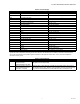
R7140G,L,M BURNER CONTROL MODULES Table 3. Terminal Ratings. Terminal No. Description Ratings G Flame Sensor Earth Ground — Earth G Earth Grounda — L2(N) Line Voltage Common — L1 Line Voltage Supply (L1) 120 Vac (+10/-15%), 50 or 60 Hz (±10%). 3 Lockout/Running Interlock 120 Vac, 8A run, 43A inrush. 4 Pre-Ignition Interlock Input 120 Vac, 1 mA. 5 Pilot Valve/Ignition 120 Vac. See Table 4. 6 Interrupted/Intermittent Pilot Valve/First Stage Oil Valve 120 Vac. See Table 4.
R7140G,L,M BURNER CONTROL MODULES Table 5. Sequence Timing for Normal Operation. Flame Establishing Period Device Initiate Standby Purge Pilot R7140G 10 sec. * ** Main Post Purge Run Timing Interlock Circuits 4 or 10 10, 15 sec. sec.a or intermittent. * Firing Rate Circuit Energy Approval Saving Code Pre-Purge Bodies 15 sec. Pre-Ignition, 4-wire No Running, Low Fire modulating UL/CSA Modulating R7140L 10 or 15 sec.a Pre-Ignition, Lockout High and Low Fire FM/IRI Modulating R7140M 10 sec.
R7140G,L,M BURNER CONTROL MODULES Location Make sure the wiring subbase of the old device is a 20-terminal Q520 (four rows of 5 terminals). Humidity Make sure the system Controller is connected to the correct terminal on the Q520 wiring subbase. It may be in a wire nut tucked into the subbase. It needs to be connected to a terminal (like terminal 4 or 16). Install the relay module where the relative humidity never reaches the saturation point.
R7140G,L,M BURNER CONTROL MODULES Table 6. J1/J2 Jumper Configuration for R4140M/PM720M. Model Purge Timer Leave J1 & J2 Remove J1 and J2 R4140M1004/M1012 A1039 X R4140M1020/M1038 A1047 X R4140M1046/M1053 A1062 X R4140M1079 (GP101) A1062 X R4140M1103/M1111 A1039 X R4140M1145/M1152 A1047 X R4140M1160/M1178 A1062 X R4140M1186 A1047 X R4140M1194 ST7800A1062 BC7000L1000 w/PM720M2002 ST7800A1062 BC7000L1000 w/PM720M2036 * X X * Check terminal 8 and 15.
R7140G,L,M BURNER CONTROL MODULES R7140G INITIATE (INITIAL POWERUP ONLY) POWER PREPURGE PFEP 10 SEC. HOLD 00 TIMED 00 DRIVE TO 00(4 SEC. IF 10 20 PREPURGE LOW FIRE STANDBY MFEP JR1 CLIPPED POWER LED DISPLAY 25 POWER POWER POWER POWER PILOT PILOT PILOT PILOT PILOT FLAME FLAME FLAME FLAME FLAME MAIN MAIN MAIN MAIN MAIN ALARM ALARM ALARM ALARM ALARM 18 IGN. 15 POSTPURGE POWER BURNER/BLOWER MOTOR BURNER 00 RUN POWER STANDBY POWER 8 5 SEC. 10 SEC. IGN./PILOT 5 15 SEC.
R7140G,L,M BURNER CONTROL MODULES L1 (HOT) L2 1 L1 120 Vac, 50/60 Hz PLUG-IN PURGE TIMER CARD CONFIGURATION JUMPERS TEST JACK FLAME SIGNAL RUN/TEST SWITCH F MICROCOMPUTER TEST RESET PUSHBUTTON PLUG-IN FLAME AMPLIFIER G 17 2K 3K RELAY DRIVE CIRCUIT 4K 5K RELAY STATUS FEEDBACK AND LINE VOLTAGE INPUTS 6K 7K 8K 9K SAFETY RELAY CIRCUIT STATUS LEDs 1K POWER SUPPLY CONTROL POWER R1 R1 LIMITS RUNNING/ LOCKOUT INTERLOCK PRE-IGNITION INTERLOCK CONTROLLER 3 16 4 L2 1K1 2K1 5K1 4K1 7K1 2
R7140G,L,M BURNER CONTROL MODULES L1 (HOT) L2 1 L1 L2 120 Vac, 50/60 Hz PLUG-IN PURGE TIMER CARD CONFIGURATION JUMPERS TEST JACK FLAME SIGNAL RUN/TEST SWITCH F MICROCOMPUTER TEST POWER SUPPLY PRE-IGNITION INTERLOCK PLUG-IN FLAME AMPLIFIER G 17 CONTROL POWER 4 RUNNING/ LOCKOUT INTERLOCK LIMITS CONTROLLER 1K1 3 16 2K1 5K1 4K1 7K1 2K2 LOW FIRE SWITCH 6K1 13 3K1 HIGH FIRE 8K1 1 COMMON 8K2 MODULATE 9K2 9K1 LOW FIRE 18 IGNITION 5 PILOT 6 PILOT/V2 7 MAIN VALVE 8 BLOWER 9 A
R7140G,L,M BURNER CONTROL MODULES FOR DIRECT SPARK IGNITION (OIL OR GAS) IGNITION TRANSFORMER TO L2 WIRING 2 SUBBASE TERMINAL STRIP (4) PREIGNITION INTERLOCK(S) 1ST STAGE FUEL VALVE 6 2ND STAGE FUEL VALVE (OPTIONAL) 7 5 SECOND IGNITION (EARLY SPARK TERMINATION) RUNNING INTERLOCKS (INCLUDING AIRFLOW SWITCH) 3 10 SECOND INTERRUPTED PILOT/IGNITION 5 4 6 3 18 BURNER CONTROLLER 4 LIMITS PILOT/IGNITION L1 MAIN FUEL VALVE(S) 17 120V ALARM 9 HIGH FIRE B R R W W SERIES 90 CONTROLLER 1
R7140G,L,M BURNER CONTROL MODULES FOR DIRECT SPARK IGNITION (OIL OR GAS) 5 IGNITION JUMPER TO 6 L2 MAIN OIL VALVE SOLENOID 4 2 WIRING SUBBASE TERMINAL STRIP (4) RUNNING INTERLOCKS (INCLUDING AIRFLOW SWITCH) 3 10 SECOND INTERRUPTED PILOT/IGNITION PREIGNITION INTERLOCK(S) LIMITS 6 120V ALARM 11 HIGH FIRE 12 15 13 B R R W W SERIES 90 CONTROLLER 14 F 5 MODULATE 8 G RECTIFYING FLAME ROD, OR INFRARED (LEAD SULFIDE) FLAME DETECTOR BLUE C7027A, C7035A, C7927 OR C7044A ULTRAVIOLET FLA
R7140G,L,M BURNER CONTROL MODULES R7140L PREPURGE PREPURGE PFEP INITIATE HOLD HOLD 10 SEC. (INITIAL 00 00 20 00 TIMED DRIVE TO DRIVE TO 00(4 SEC. IF 10 POWERUP PREPURGE LOW FIRE JR1 CLIPPED STANDBY MFEP HIGH FIRE ONLY) POWER POWER POWER LED DISPLAY 25 POWER POWER POWER POWER PILOT PILOT PILOT PILOT PILOT FLAME FLAME FLAME FLAME FLAME MAIN MAIN MAIN MAIN MAIN ALARM ALARM ALARM ALARM ALARM 18 IGN.
R7140G,L,M BURNER CONTROL MODULES L1 (HOT) L2 1 L1 120 Vac, 50/60 Hz CONFIGURATION JUMPERS PLUG-IN PURGE TIMER CARD TEST JACK FLAME SIGNAL RUN/TEST SWITCH F MICROCOMPUTER TEST RESET PUSHBUTTON PLUG-IN FLAME AMPLIFIER G 17 2K 3K RELAY DRIVE CIRCUIT 4K 5K RELAY STATUS FEEDBACK AND LINE VOLTAGE INPUTS 6K 7K 8K 9K SAFETY RELAY CIRCUIT STATUS LEDs 1K POWER SUPPLY R1 LIMITS CONTROLLER PII 4 RUNNING/ LOCKOUT INTERLOCK 1K1 2K1 16 (3) LOW FIRE SWITCH 4K1 13 (D) HIGH FIRE SWITCH 7K1 2K2 1
R7140G,L,M BURNER CONTROL MODULES L1 (HOT) L2 1 L1 L2 120 Vac, 50/60 Hz CONFIGURATION JUMPERS PLUG-IN PURGE TIMER CARD TEST JACK FLAME SIGNAL RUN/TEST SWITCH F MICROCOMPUTER TEST RESET PUSHBUTTON PLUG-IN FLAME AMPLIFIER G 17 2K 3K 4K RELAY 5K DRIVE CIRCUIT 6K RELAY STATUS FEEDBACK AND LINE VOLTAGE INPUTS 7K 8K 9K SAFETY RELAY CIRCUIT STATUS LEDs 1K POWER SUPPLY CONTROL POWER PRE-IGNITION INTERLOCK 4 RUNNING/ LOCKOUT INTERLOCK LIMITS CONTROLLER 1K1 3 16 2K1 5K1 4K1 LOW FIRE SWITCH 1
R7140G,L,M BURNER CONTROL MODULES FOR DIRECT SPARK IGNITION (OIL OR GAS) IGNITION TRANSFORMER 5 6 TO L2 JUMPER MAIN FUEL VALVE WIRING SUBBASE TERMINAL STRIP (4) 5 SECOND IGNITION (EARLY SPARK TERMINATION) 2 LOCKOUT INTERLOCKS (INCLUDING AIRFLOW SWITCH) 3 10 SECOND INTERRUPTED PILOT/IGNITION 5 18 15 SECOND INTERRUPTED PILOT/IGNITION 6 17 MAIN FUEL VALVE(S) 7 PREIGNITION INTERLOCKS BURNER CONTROLLER 4 120V ALARM 9 4 LIMITS L1 7 L2 BURNER MOTOR (BLOWER) 16 10 11 HIGH FIRE 12 HIG
R7140G,L,M BURNER CONTROL MODULES FOR DIRECT SPARK IGNITION (OIL OR GAS) IGNITION TRANSFORMER 5 6 TO L2 JUMPER MAIN FUEL VALVE (S) WIRING 2 SUBBASE TERMINAL STRIP (4) 5 SECOND IGNITION (EARLY SPARK TERMINATION) LOCKOUT INTERLOCKS (INCLUDING AIRFLOW SWITCH) 3 10 SECOND INTERRUPTED PILOT/IGNITION 5 18 15 SECOND INTERRUPTED PILOT 6 17 MAIN FUEL VALVE(S) 7 16 BURNER MOTOR (BLOWER) PREIGNITION INTERLOCKS BURNER CONTROLLER 4 LIMITS 120V ALARM 9 10 11 HIGH FIRE L1 L2 12 13 B R R
R7140G,L,M BURNER CONTROL MODULES R7140M INITIATE (INITIAL POWERUP ONLY) POWER LED DISPLAY PREPURGE PFEP HOLD 10 SEC. 00 TIMED 00 DRIVE TO 00(4 SEC. IF 10 20 PREPURGE LOW FIRE STANDBY MFEP JR1 CLIPPED POWER 25 POWER POWER POWER POWER PILOT PILOT PILOT PILOT PILOT FLAME FLAME FLAME FLAME FLAME MAIN MAIN MAIN MAIN MAIN ALARM ALARM ALARM ALARM ALARM 18 IGN. 15 POSTPURGE STANDBY POWER BURNER/BLOWER MOTOR BURNER 00 RUN POWER POWER 8 5 SEC. 10 SEC. IGN.
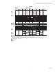
R7140G,L,M BURNER CONTROL MODULES L2 L1 L2 L1 CONFIGURATION JUMPERS PURGE TIMER 17 F FLAME AMPLIFIER G INTERNAL ELECTRONICS 3K1 1R1 6K1 START INTERLOCKS 13 4 LIMITS 9 ALARM 8 BLOWER LF 1R1 16 CONTROLLER AIRFLOW 2K1 5K1 1K1 3 4K1 11 J1 7K1 12 8K2 9K1 J2 10 18 IGN XFMR 5 INTERMITTENT PILOT 6 15 SECOND INTERMITTENT PILOT VALVE 7 MAIN VALVE 2K2 9K2 M23335 14 Fig. 15. Internal block diagram of the R7140M1007 with start interlocks. (See Fig. 17 for detailed wiring.
R7140G,L,M BURNER CONTROL MODULES FOR DIRECT SPARK IGNITION OF OIL OR GAS TO L2 WIRING 2 SUBBASE TERMINAL STRIP (4) IGNITION 5 1ST STAGE FUEL VALVE 6 2ND STAGE FUEL VALVE (OPTIONAL) 7 RUNNING INTERLOCKS (INCLUDING AIRFLOW SWITCH) 3 4 5 SECOND IGNITION (EARLY SPARK TERMINATION) 3 10 SECOND INTERRUPTED PILOT/IGNITION 5 17 INTERMITTENT PILOT 6 16 MAIN FUEL VALVE(S) 7 18 BURNER CONTROLLER 4 LIMITS 120V ALARM 9 DAMPER CONTROL 5 10 L1 L2 7 12 11 13 8 14 F L1 (HOT) 8 LOW FIRE S
R7140G,L,M BURNER CONTROL MODULES 4 FOR DIRECT SPARK IGNITION (OIL OR GAS) IGNITION TRANSFORMER TO L2 2 WIRING SUBBASE TERMINAL STRIP (4) 3 (P) 4 (13) PREIGNITION INTERLOCKS BURNER CONTROLLER LIMITS ALARM INTERMITTENT PILOT/IGNITION 6 L2 17 MAIN FUEL VALVE(S) 7 6 DAMPER CONTROL 3 16 (3) 11 13 15 (10) (D) (8) L1 (HOT) L2 F 14 (S1) (12) BURNER MOTOR 8 (M) LOW FIRE SWITCH G (S2) RECTIFYING FLAME ROD OR INFRARED (LEAD SULFIDE) 5 FLAME DETECTOR MASTER SWITCH OR BLUE 1 POWER
R7140G,L,M BURNER CONTROL MODULES SAFETY SHUTDOWN Safety Shutdown (Lockout) occurs if any of the following occur during the indicated period: 1. 2. 3. 4. 5. 6. INITIATE Period: a. Purge card is not installed or is removed. b. Purge card is bad. c. Configuration jumpers are changed (after 200 hours of operation). d. AC line power errors occur; see Operation section. e. Four minute INITIATE period has been exceeded. STANDBY Period: a. Flame signal is present after 240 seconds. b.
R7140G,L,M BURNER CONTROL MODULES Normal Start-Up Pre-Purge 2. The R7140 provides a pre-purge timing selectable from two seconds to 30 minutes with power applied and the R7140 operating control indicating a call for heat: a. Running Interlocks, Pre-Ignition Interlocks, Burner Switch, Run/Test Switch, Lockout Interlocks and all microcomputer monitored circuits must be in the correct operating state. b. The blower motor output, terminal 8, is powered to start the PREPURGE sequence.
R7140G,L,M BURNER CONTROL MODULES 1. 2. 3. 4. 5. SETTINGS AND ADJUSTMENTS In Pre-Purge Drive To High Fire Position (R7140L), the Run/Test Switch, when placed in the TEST position, holds in PREPURGE with the firing rate motor in the High Fire position. In the measured PREPURGE sequence, the Run/Test Switch, when placed in the TEST position, causes the PREPURGE timing to stop. The firing rate motor is in the High Fire position.
R7140G,L,M BURNER CONTROL MODULES STATIC CHECKOUT 3. After checking all wiring, perform this checkout before installing the R7140 on the subbase. These tests verify the Q520A Wiring Subbase is wired correctly, and the external controllers, limits, interlocks, actuators, valves, transformers, motors and other devices are operating properly. General Instructions 1. 2. 3. WARNING 4. Explosion and Electrical Shock Hazard. Can cause serious injury, death, or equipment damage. 1.
R7140G,L,M BURNER CONTROL MODULES Table 8. Static Checkout. (Continued) Test No. Test R7140 Models Jumpers Voltmeter Normal Operation If Operation is Abnormal, Check the Items Listed Below L1-5 — 1. Watch for spark or listen for buzz. 1. Ignition spark (if ignition a. Ignition electrodes are clean. transformer is connected to b. Ignition transformer is okay. terminal 5). 2. Automatic pilot valve opens (if 2. Listen for click or feel head of valve for activation. connected to terminal 5). a.
R7140G,L,M BURNER CONTROL MODULES SYSTEM CHECKOUT Limit trial for pilot to ten seconds. Limit the attempt to light main burner to two seconds after fuel reaches burner nozzle. Do not exceed manufacturer nominal lightoff time. IMPORTANT Perform all Static Checkout Procedures for the applicable relay module shown in Table 8 before starting these procedures. CAUTION Equipment Malfunction or Damage Hazard. Incorrect wiring can cause equipment damage. Each relay module type is unique.
R7140G,L,M BURNER CONTROL MODULES 7. 8. 9. 10. 11. Power is connected to the system disconnect switch (master switch). Lockout is reset (reset button) only if the Relay Module is powered. Run/Test Switch (if present) is in RUN position. System is in STANDBY condition. STANDBY message is displayed in the S7800 Keyboard Display Module. All limits and interlocks are reset. Flame Signal Measurement See instructions provided with the amplifier. INITIAL LIGHTOFF CHECKS 7.
R7140G,L,M BURNER CONTROL MODULES 20. 21. 22. 16. Run the burner through another sequence, observing the flame signal for: a. Pilot flame alone. b. Pilot and main flame together. c. Main flame alone (unless monitoring an intermittent pilot). Also observe the time it takes to light the main flame. Ignition of main flame should be smooth. Make sure all readings are in the required ranges before proceeding. Return the system to normal operation. 17. 18.
R7140G,L,M BURNER CONTROL MODULES 6. IGNITION INTERFERENCE TEST (ALL FLAME RODS) After the PILOT LED turns on in interrupted pilot applications, set the Run/Test Switch to the TEST position to stop the sequence. The FLAME LED comes on when the pilot ignites. NOTE: Ignition interference can subtract from (decrease) or add to (increase) the flame signal. If it decreases the flame signal enough, it causes a safety shutdown.
R7140G,L,M BURNER CONTROL MODULES If hot refractory saturation occurs, the condition must be corrected. Add an orifice plate in front of the cell to restrict the viewing area, lengthen the sight pipe or decrease the pipe size (diameter). Continue adjustments until hot refractory saturation is eliminated.
R7140G,L,M BURNER CONTROL MODULES 8. 9. If the response time is still too slow, replace the Plug-in Flame Signal Amplifier. If the detector is relocated or resighted, or the amplifier is replaced, repeat all required Checkout tests. SAFETY SHUTDOWN TESTS (ALL INSTALLATIONS) 6. Perform these tests at the end of Checkout, after all other tests are completed. If used, the external alarm should turn on. Press the RESET pushbutton on the relay module to restart the system. 1. 2. 3. 4. 5.
R7140G,L,M BURNER CONTROL MODULES 66-1153—03 34
R7140G,L,M BURNER CONTROL MODULES 35 66-1153—03
R7140G,L,M BURNER CONTROL MODULES Automation and Control Solutions Honeywell International Inc. 1985 Douglas Drive North Golden Valley, MN 55422 customer.honeywell.com ® U.S. Registered Trademark © 2013 Honeywell International Inc. 66-1153—03 M.S. Rev.