HRHD 410 4-Channel Digital Video Recorder User Guide Document 900.0315 – 02/07 – Rev 3.
Revisions Issue Date Revisions 1.00 11/04 New document. 1.01 04/05 Update template, styles and contact information. 2.00 07/05 Add Waste Electrical Equipment warning. 3.
FCC Compliance Statement INFORMATION TO THE USER: This equipment has been tested and found to comply with the limits for a Class A digital device, pursuant to part 15 of the FCC rules. These limits are designed to provide reasonable protection against harmful interference when the equipment is operated in a commercial environment.
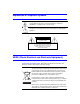
Explanation of Graphical Symbols This symbol alerts the user to the presence of uninsulated dangerous voltage within the product's enclosure that may be of sufficient magnitude to constitute a risk of electric shock. This symbol alerts the user to the presence of important operating and maintenance (servicing) instructions in the literature accompanying the appliance. WARNING RISK OF ELECTRIC SHOCK DO NOT OPEN WARNING: TO REDUCE THE RISK OF ELECTRIC SHOCK, DO NOT REMOVE COVER (OR BACK).
Contents Contents FCC Compliance Statement . . . . . . . . . . . . . . . . . . . . . . . . . . . . . . . . . . i Explanation of Graphical Symbols . . . . . . . . . . . . . . . . . . . . . . . . . . . . . . ii WEEE (Waste Electrical and Electronic Equipment). . . . . . . . . . . . . . . . . . . . . ii About This Document . . . . . . . . . . . . . . . . . . . . . . . . . . . . . . . . . . . . . xiii Overview of Contents . . . . . . . . . . . . . . . . . . . . . . . . . . . . . . . . . . . .
Contents System Check Screen . . . . . . . . . . . . . . . . . . Storage Screen . . . . . . . . . . . . . . . . . . . . . . System Log Screen . . . . . . . . . . . . . . . . . . . . System Shutdown . . . . . . . . . . . . . . . . . . . . Configuring Input Devices . . . . . . . . . . . . . . . . . . . . . Camera Setup Screen . . . . . . . . . . . . . . . . . . Alarm In Setup Screen . . . . . . . . . . . . . . . . . . Motion Detector . . . . . . . . . . . . . . . . . . . . . . Text In Setup Screen . . . . . .
Contents Searching Video . . . . . . Date/Time Search. Calendar Search . Event Search . . . Text-In Search. . . Appendix A . . . . . . . . . . . . . . . . . . . . . . . . . . . . . . . . . . . . . . . . . . . . . . . . . . . . . . . . . . . . . . . . . . . . . . . . . . . . . . . . . . . . . . . . . . . . . . . . . . . . . . . . . . . . . . . . . . . . . . . . . . . . . . . . . . . . . . . . . . . . . . . . . . . . . . . . . . . . . . . . . 85 . 86 . 86 . 87 .
Contents Rev 3.03 vi Document 900.
Figures Figures Figure 1-1 Typical DVR Installation . . . . . . . . . . . . . . . . . . . . . . . . . . . . . . 2 Figure 2-1 DVR Rear Panel . . . . . . . . . . . . . . . . . . . . . . . . . . . . . . . . . . 6 Figure 2-2 Video Input Connectors . . . . . . . . . . . . . . . . . . . . . . . . . . . . . . 6 Figure 2-3 Video Loop Through Connectors . . . . . . . . . . . . . . . . . . . . . . . . . 6 Figure 2-4 Audio In and Out Connectors . . . . . . . . . . . . . . . . . . . . . . . . . . .
Figures Figure 3-18 Camera Setup Screen . . . . . . . . . . . . . . . . . . . . . . . . . . . . . . . 34 Figure 3-19 PTZ Device List . . . . . . . . . . . . . . . . . . . . . . . . . . . . . . . . . . 35 Figure 3-20 Alarm In Screen . . . . . . . . . . . . . . . . . . . . . . . . . . . . . . . . . . 36 Figure 3-21 Motion Detector Screen . . . . . . . . . . . . . . . . . . . . . . . . . . . . . . 36 Figure 3-22 Motion Detection Zone Screen . . . . . . . . . . . . . . . . . . . . . . . . . .
Figures Figure 3-61 Load / Save Setup Screen . . . . . . . . . . . . . . . . . . . . . . . . . . . . . 75 Figure 4-1 DVR Front Panel . . . . . . . . . . . . . . . . . . . . . . . . . . . . . . . . . . 78 Figure 4-2 Live Monitoring (Text-In) Screen. . . . . . . . . . . . . . . . . . . . . . . . . . 79 Figure 4-3 PTZ Menu Screen . . . . . . . . . . . . . . . . . . . . . . . . . . . . . . . . . 80 Figure 4-4 PTZ Preset Screen . . . . . . . . . . . . . . . . . . . . . . . . . . . . . . . . .
Figures Rev 3.03 x Document 900.
Tables Tables Table 3-1 Front Panel LEDs and Controls. . . . . . . . . . . . . . . . . . . . . . . . . . . 18 Table 3-2 Motion Detection Zone Choices . . . . . . . . . . . . . . . . . . . . . . . . . . 37 Table 4-1 Playback Controls . . . . . . . . . . . . . . . . . . . . . . . . . . . . . . . . . 83 Table F-1 Technical Specifications . . . . . . . . . . . . . . . . . . . . . . . . . . . . . 103 Rev 3.03 xi Document 900.
Tables Rev 3.03 xii Document 900.
About This Document This document introduces the HRHD 410 4-channel Digital Video Recorder (DVR) and describes how to install, configure, and operate the DVR. Overview of Contents This document contains the following chapters and appendixes: • • • • • • • • • • Rev 3.03 Chapter 1, Introduction, introduces the HRHD 4-channel DVR, lists the features, and gives a functional overview of the components. Chapter 2, Installation, describes how to install the DVR and connect the system components.
Important Safeguards 1. Read Instructions All the safety and operating instructions should be read before the appliance is operated. 2. Retain Instructions The safety and operating instructions should be retained for future reference. 3. Cleaning Unplug this equipment from the wall outlet before cleaning it. Do not use liquid aerosol cleaners. Use a damp soft cloth for cleaning. 4.
9. Lightning For added protection for this equipment during a lightning storm, or when it is left unattended and unused for long periods of time, unplug it from the wall outlet and disconnect the antenna or cable system. This will prevent damage to the equipment due to lightning and power-line surges. 10. Overloading Do not overload wall outlets and extension cords to avoid the risk of fire or electric shock. 11.
17. Correct Batteries WARNING! Risk of explosion if battery is replaced by an incorrect type. Dispose of used batteries according to the instructions. 18. Operating Temperature An operating temperature range is specified (see Appendix F, Specifications) so that the customer and installer may determine a suitable operating environment for the equipment. 19.
Introduction 1 Introduction Features Your color digital video recorder (DVR) provides recording capabilities for 4 camera inputs. It provides exceptional picture quality in both live and playback modes, and offers the following features: • • • • • • • • • • • • • • Rev 3.
Introduction Figure 1-1 Typical DVR Installation Multi-screen Monitor VGA Monitor Sensors 1–4 1–4 cameras VGA Spot Siren Audio input 1–4 Alarm output Audio output Digital Video Recorder Flashing light Internal CD-RW ATM/POS USB backup device Technical Overview Your DVR can replace both a time-lapse VCR and a multiplexer in a security installation. However, it has many features that make it much more powerful and easier to use than even the most advanced VCR.
Introduction The DVR can be set up to alert you when the hard disk drive is full or it can be set up to record over the oldest video after the disk is full. Your DVR uses a proprietary encryption scheme making it nearly impossible to alter video. You can view live video, search for images, and control your DVR remotely by connecting via external modem or Ethernet. You can use the USB port to copy video clips to USB-IDE hard disk drives, USB CD-RW drives, or flash drives. Rev 3.03 3 Document 900.
Introduction Rev 3.03 4 Document 900.
Installation 2 Installation This chapter covers how to connect the DVR to peripheral equipment.
Installation Figure 2-1 DVR Rear Panel Video in Video out SVHS out Alarm in CAUTION RISK OF ELECTRIC SHOCK DO NOT OPEN ! CAUTION:TO REDUCE THE RISK OF ELECTRIC SHOCK, DO NOT REMOVE COVER (OR BACK). NO USER-SERVICEABLE PARTS INSIDE.
Installation Note The Loop BNC connectors are auto terminated. Do not connect a cable to the Loop BNC unless it is connected to another terminated device because it will cause poor quality video. Connecting Audio Note It is your responsibility to determine if local laws and regulations permit recording audio. Figure 2-4 AUDIO IN 1 Audio In and Out Connectors AUDIO IN 2 AUDIO IN 3 AUDIO IN 4 AUDIO OUT Your DVR can record audio. 1. Connect the audio source to Audio In. 2.
Installation Setting Unit for CVBS (SVHS) or VGA Output Figure 2-5 CVBS (SVHS) VGA Switch CVBS SVHS VGA Set the switch to CVBS (SVHS) or VGA for monitor output. Select CVBS (SVHS) for a spot monitor or VGA for an RGB monitor. Make sure you set the CVBS (SVHS) or VGA selector switch before turning on the DVR. You cannot change the setting while the unit is running. Rev 3.03 Note The DVR may not support some LCD monitors. Also, some monitors do not support Multi Sync.
Installation Connecting the Monitor Connecting the Spot Monitor Figure 2-6 Video Out Connectors VIDEO OUT SVHS OUT Connect the Spot Monitor to either the Video Out or SVHS Out connector. Note For Spot Monitor output, set the CVBS (SVHS) VGA selector to CVBS (SVHS) (see Figure 2-5). If your monitor has an SVHS input, use it to give you better quality video display. Note The Video Out (BNC) and the SVHS Out connectors may be connected to individual monitors for simultaneous operation.
Installation Note For RGB Monitor output, set the CVBS (SVHS) VGA selector switch to VGA (see Figure 2-5). Connecting to the Network Port Figure 2-8 Network Connector NETWORK The DVR can be networked using the 10/100Mb Ethernet connector. Connect a CAT5 cable with an RJ45 jack to the DVR connector. The DVR can be networked with a computer for remote monitoring, searching, configuration, and software upgrades. See Chapter 3, Configuration for configuring the Ethernet connections.
Installation Note The DVR is not supplied with a modem cable, and many modems are not supplied with cables. Make certain you have the correct cable when purchasing the modem. Factory Reset Figure 2-10 Factory Reset Switch RS - 232C Factory reset switch The DVR has a Factory Reset switch to the right of the RS232C connector. This switch will only be used on the rare occasions that you want to return all the settings to the original factory default settings.
Installation Note 5. When the DVR successfully resets to factory defaults all the LEDs on the front panel flash three times. Release the reset switch. All of the DVR settings are now at the original settings it had when it left the factory. Connecting Alarms Figure 2-11 Alarm Input Connector Strips AI1 AI2 AI3 AI4 GND ARI To make connections on the Alarm Connector Strip: 1. Press and hold the button. 2. Insert the wire in the hole below the button. 3.
Installation ARI (Alarm Reset In) An external signal to the Alarm Reset In (ARI) can be used to reset both the Alarm Out signal and the DVR internal buzzer. Mechanical or electrical switches can be wired to the ARI (Alarm In) and GND (Ground) connectors. The threshold voltage is below 0.3V and should be stable at least 0.5 seconds to be detected. Connect the wires to the ARI (Alarm Reset In) and GND (Ground) connectors.
Installation Connecting to the USB Port Figure 2-14 USB Connector USB Use the USB port to connect external hard disk drives, CD-RW drives, or flash drives for archiving video. 1. Position the external hard disk drive close enough to the DVR so that you can make the cable connections, usually less than 6 feet (1.83 m). 2. Use the USB cable provided with the hard disk drive or CD-RW to connect it to the DVR.
Installation WARNING! Route power cords so they are not a tripping hazard. Make certain the power cord will not be pinched or abraded by furniture. Do not install power cords under rugs or carpet. The power cord has a grounding pin. If your power outlet does not have a grounding pin receptacle, do not modify the plug. Do not overload the circuit by plugging too many devices into one circuit. Your DVR is now ready to operate. See Chapter 3, Configuration and Chapter 4, Operation. Rev 3.
Installation Rev 3.03 16 Document 900.
Configuration 3 Configuration This chapter covers the following topics: • • • • • • • • Front panel controls and LEDs Initial unit setup Configuring input devices Configuring recording settings Configuring event action Configuring on-screen display Configuring network setup Configuring password setup Note Ensure that your DVR is completely installed before proceeding. See Chapter 2, Installation. Front Panel Controls Figure 3-1 DVR Front Panel (4-Channel DVR Shown) Cameras Internal CD-RW Rev 3.
Configuration Many of the buttons have multiple functions. Table 3-1 describes each button and control. Take a few minutes to review the descriptions. You will use these to initially set up your DVR and for daily operations. Note Table 3-1 Front panel There is no separate Alarm button. Pressing any key on the front panel resets alarm output, including the internal buzzer when the alarm is activated.
Configuration Table 3-1 Front panel PTZ buttons Front Panel LEDs and Controls (cont’d) Function • • • Opens a Pan/Tilt/Zoom screen that allows you to control properly configured PTZ cameras. In PTZ mode, pressing PTZ enters the Digital Zoom mode. Press PTZ again in Digital Zoom mode to return to Live Monitoring mode. When a PTZ device is not installed, press PTZ to enter the Digital Zoom mode directly. Press PTZ in Playback mode to enter the Digital Zoom Playback mode.
Configuration Table 3-1 Front panel Front Panel LEDs and Controls (cont’d) Function Shuttle Ring The Shuttle Ring only functions in Playback mode. The Shuttle Ring is spring loaded. When released, the video pauses and the ring returns to the center position. Turn the ring clockwise to play video forward. Turn the ring counterclockwise to play video backward. Playback speed varies with the amount the ring is turned. The playback speeds are Wx0.5, WW, WWW, WWWW, Xx0.5, X, XX, XXX, and XXXX.
Configuration Figure 3-2 2. Admin Password Screen Enter the password by pressing the appropriate combination of Camera buttons and then ENTER ( ). The factory default password is 4321. There are two Setup screens: Quick Setup and Normal Setup. The factory default is the Quick Setup screen. Quick Setup Screen Figure 3-3 Quick Setup Screen Use the Quick Setup screen to set up the most commonly used features of your DVR. Use the Arrow buttons to move through the options.
Configuration Note It is your responsibility to determine if local laws and regulations permit recording audio. 5. Highlight the box beside Sequence Dwell Time and select from 3 to 60 seconds for the camera sequence dwell time. 6. Selecting System Information… enters a screen that allows you to set the site name, set the language and view various system operational parameters. 7. Selecting Storage… enters a screen where you can check the storage status. 8.
Configuration Normal Setup Screen Figure 3-4 Normal Setup Screen Press MENU to enter the Normal Setup screen. If the Quick Setup screen displays, turn it off as described above. The Normal Setup screen gives you access to all the DVR setup screens. System Information Use the System Information screen to name the Site Description (name), assign a unit ID number, select the language to use, and upgrade the software. Highlight System Information (MENU ➤ System ➤ System Information) and press .
Configuration Figure 3-6 2. Highlight the box beside Site Description and press . A virtual keyboard displays. Figure 3-7 3. System Information Change Screen Virtual Keyboard Use the Arrow keys to highlight the first character you want in the Site Title field and then press . That character appears in the title bar and the cursor moves to the next position. You can use up to 20 characters including spaces in your title. Press to toggle between the upper and lower case keyboards.
Configuration 6. The box beside H/W Version and S/W Version displays current hardware and software versions of the DVR. Note You can upgrade the software only in the System Information Change screen. Only the System Administrator can upgrade the software. You cannot upgrade the software during clip copy. To upgrade the software: a. Connect the USB device containing the upgrade package file to the DVR. Highlight Upgrade… and press .
Configuration Note Only the system administrator can upgrade the software. You cannot upgrade the software during clip copy. 7. You can save your changes by highlighting OK and pressing . Selecting Cancel exits the screen without saving the changes. Date/Time Setup Highlight Date/Time in the Main Menu (MENU ➤ System ➤ Date/Time) and then press . The Date/Time setup screen displays. Figure 3-9 Caution 1.
Configuration Note The clock will not start running until you have restarted the unit, so you may wish to set the time last. 3. Highlight the box beside Time Zone and press . Select the time zone you are in from the list and press . 4. Highlight the box beside Daylight Saving Time and press . Pressing toggles between On and Off. 5. Highlight the Holiday Setup… box and press . You can set up holidays by highlighting Add: and pressing . The current date displays. 6.
Configuration Figure 3-11 Time Sync Screen Highlight the box beside Automatic Time Sync and then press to toggle between On and Off. Highlight the box beside SNTP Server and then press . Change the numbers by highlighting them and using the Up and Down arrows to increase or decrease the number value. Highlight the box beside Interval and then press . Set the time interval for synchronization from 30 to 300 minutes. The box beside System Clock displays the DVR time setting.
Configuration Note When the time difference between the DVR and the time server is more than one minutes, the DVR might not synchronize the time to prevent any unexpected loss of recorded video data. If you want to synchronize the time manually, select Now… . Highlight the Run as Server box and then press to toggle between On and Off. When it is On, the DVR you are setting up runs as a time server. To save your changes, highlight OK and then press .
Configuration 1. Highlight the box under the On/Off heading and then press . This toggles between On and Off. When it is On, the DVR reports a fault condition if it does not detect any recording or if there is no alarm during the designated time. 2. Highlight the box under the Interval heading and then press . A slide bar displays allowing you to set the check interval from 1 Hour to 30 Days by using the Left and Right Arrow buttons. 3. The Status field displays the fault conditions.
Configuration Storage Screen Highlight Storage in the Main Menu (MENU ➤ System ➤ Storage) and then press . The Storage setup screen displays. Figure 3-14 Storage Screen The Type field displays the type and capacity of storage devices. The Status field displays the device status or fault conditions. Options are: Good Disk Bad S.M.A.R.T. Alert High Temperature Not installed Note If the DVR senses S.M.A.R.T (Self-Monitoring, Analysis and Reporting Technology), Alert, or High Temperature, the S.M.A.R.T.
Configuration 2. Highlight S.M.A.R.T. Setup... and then press . The S.M.A.R.T. Setup screen displays. Note If no hard disk drives are installed in the DVR, the S.M.A.R.T. Setup… button is disabled. Figure 3-15 S.M.A.R.T. Setup Screen Your DVR shows the conditions of hard disk drives when the installed IDE hard disk drives support S.M.A.R.T. Monitoring program. a. Highlight the box beside Use. Press to toggle between On and Off. b.
Configuration System Log Screen Highlight System Log in the Main Menu (MENU ➤ System ➤ System Log) and then press . The System Log screen displays. Figure 3-16 System Log Screen The System Log screen displays a record of various events logged by the DVR. The list shows the dates and times the system was turned ON and OFF, the system was restarted, recording was started or stopped, playback was started or stopped, setup changes were made, and data banks were cleared.
Configuration Configuring Input Devices Use the Device menu (MENU ➤ Device) to configure the video, audio, and remote control devices connected to the DVR. Figure 3-17 Device Menu Camera Setup Screen Use the Camera Setup screen to turn each camera on or off and to hide the video associated with that camera number. Highlight Camera in the Device menu (MENU ➤ Device ➤ Camera) and then press . The Camera setup screen displays. Figure 3-18 Rev 3.03 Camera Setup Screen 34 Document 900.
Configuration 1. To hide the video associated with a camera number, highlight the camera Setup heading and then press . You can select the Setup field for one specific camera or select the Setup heading to change the settings for all four cameras at once. Select from the following options in the drop-down list: On, Off, Covert 1, Covert 2 Note When you select Covert 1, the DVR displays the camera title and status icons on the covert video.
Configuration Figure 3-20 Alarm In Screen You can turn each input On (via Alarm I/O or Camera Alarm) or Off. Each input can be given a title, and the inputs can be set as NO (normally open) or NC (normally closed) independently. Motion Detector Your DVR has a built-in video motion detector. Use the Motion Detector screen to turn video motion detection On or Off for each camera and to define the area of the image where you want to detect motion.
Configuration Figure 3-22 Motion Detection Zone Screen The Motion Detection Zone screen is laid over the video for the selected camera. You can set up motion detection zones by selecting or clearing blocks. Note You can activate or deactivate four cells at a time using the button. After four cells are highlighted, if you hold the button down until the color of the highlighted cell changes from blue to yellow, you can select individual cells by using the camera buttons.
Configuration Figure 3-23 Rev 3.03 Text-In Setup Screen Note If networking is configured by the external modem, the text-in cannot be set up. Set the DVR for LAN connections and set up text-in for the RS232C port. Note Text-in data will not be recorded during clip copy. 1. To set the DVR to display the text-in information, highlight the box beside Use Text-In and press to toggle between On and Off. 2. Highlight the box under the Product Type heading and then press .
Configuration Figure 3-24 Text-In (Generic Text) Setup Screen Figure 3-25 Text-In (EPSON-POS) Setup Screen 3. Highlight the box beside Transaction Start and then press . A virtual keyboard (see Figure 3-7) displays. Enter the transaction start string. Refer to the device manufacturer’s documentation for the text string that the device first sends when a transaction starts. 4. If you want the DVR to react to any character sent from the text input device, turn on Any Character.
Configuration 8. Highlight the box beside Line Delimiter and press . In the virtual keyboard, enter the character(s) that the device uses to indicate the end of a line. Control characters can be created using ^and a capital letter (for example, ^J for NL [New Line], ^M for CR [Carriage Return]). Refer to the device manufacturer’s documentation for Line Delimiter character(s). 9. Highlight the box beside Ignore String and then press .
Configuration To give each alarm output its own title, highlight the box under the Title heading and then press . A virtual keyboard displays (see Figure 3-7) allowing you to enter the title. Highlight the Sched field and press to open a schedule screen. You can schedule alarm output in 30-minute increments from 0:00 to 24:00. Figure 3-27 Alarm Out Schedule Screen You can select individual blocks of time, entire days of the week, entire blocks of time, or the entire schedule.
Configuration Figure 3-28 Audio Setup Screen 1. Highlight the box beside Audio Recording and then press . This toggles between On and Off. When it is On, the DVR also records audio when it is recording video. 2. Highlight the box beside Mute and then press . This toggles between On and Off. When it is On, the DVR does not play live or recorded audio. 3. The DVR supports four audio inputs. You can set up each input.
Configuration Figure 3-29 RS232/RS485 Screen 1. Highlight the field for the settings you wish to make. Select the correct Baud Rate, Parity, Data Bit, and Stop Bit for the device you are connecting to the DVR. 2. For RS232, it is possible to select either Remote Control, External Modem, or Text-In in the Usage field. For RS485, it is possible to select either Remote Control or PTZ Control in the Usage field. Rev 3.
Configuration Configuring Recording Settings Note When the DVR is recording video, the REC LED on the front panel is lit and a red dot appears on the monitor. Your DVR offers a variety of flexible recording modes: • • • You can set it up to record all the time or to only record events. It can be set up to continue recording after the hard disk drive is full by recording over the oldest video. You can set it up to alert you when the hard disk is full and stop recording.
Configuration Note 2. The maximum recording speed is 30 images per second (25 ips for PAL) when the resolution is set to Standard. However, when set to High, the recording speed will decrease to 15 images per second (12.5 ips for PAL). Highlight the box beside End Of Disk and then press . This toggles between Overwrite and Stop. In Overwrite mode, the DVR continues recording when the hard disk drive is full by overwriting the oldest video.
Configuration Caution 6. When the End of Disk is set to Stop, the DVR will NOT restart recording, even after video recorded earlier than the user-defined period is deleted. To save your changes, highlight OK and then press . Selecting Cancel exits the screen without saving the changes. Time-Lapse Record Mode Setup Screen Access the Time-Lapse Record Setup screen (MENU ➤ Record ➤ Time-Lapse Record). The Time-Lapse Record Setup screen displays. Figure 3-31 1.
Configuration 3. You can set the DVR to record video based on Time-lapse Recording Schedule defined during Time-Lapse Record Setup. Highlighting the box beside Time-Lapse Recording and pressing toggles between On and Off. 4. You can set the maximum amount of time-lapse video to be stored. After the DVR reaches this amount, it will start recording over the oldest time-lapse video. The time-lapse video is stored separate from Event video.
Configuration Note The Holiday (H) schedule applies to the dates you established as holidays when setting Date/Time. To save your changes, highlight OK and then press . Select Cancel to exit the screen without saving the changes. Pre-Event Recording Setup Screen When the DVR is in the Event Record mode it is possible to have it record images before the event occurs. Use the Pre-Event Record Setup screen (MENU ➤ Record ➤ Pre-Event Record) to define how to handle pre-event recording.
Configuration Note When the DVR is in the Time-Lapse mode, it ignores the pre-event settings and follows the time-lapse settings. In this case, Pre-Event time will not be added to the Event clip. Event Action Setup You can program the DVR to record, activate the alarm output, and/or notify the remote site whenever sensor, motion, text, or video loss events are detected.
Configuration Note You can associate multiple cameras with a sensor (Alarm Input). 3. Highlight the Speed box and select number of images per second you would like to record from the drop-down list. 4. Highlight the Quality box and select the image quality you want to record from the drop-down list. 5. Highlight the Dwell Time box and set the length of time you would like to record for the associated event.
Configuration Figure 3-36 Alarm In Event Action (Notify) Setup Screen 1. Highlight the Sched box and then press . A schedule screen displays. Set the schedule as described earlier. 2. Highlight the Notify box and then press . This toggles between On and Off. When it is On, the DVR notifies the remote site when certain events occur based on a defined schedule. Note For the Notify action to work, the DVR should be registered in the RAS (Remote Administration System).
Configuration 1. Highlight the Sched box and then press . A schedule screen displays. Set the schedule as described earlier. 2. Highlight the Camera box and then press . A camera selection screen displays. Select the camera number you would like to associate with the camera that has detected motion. Note You can associate multiple cameras with a camera that detects motion. 3. Highlight the Speed box and select number of images per second you would like to record from the drop-down list. 4.
Configuration Motion Detector Event Action (Notify) Setup Screen Use this screen to set the DVR to notify the remote site when certain motion events are activated. Figure 3-39 Motion Detector Event Action (Notify) Screen 1. Highlight the Sched box and then press . A schedule screen displays. Set the schedule as described earlier. 2. Highlight the Notify box and then press . This toggles between On and Off.
Configuration Figure 3-40 Text-In Event Action (Record) Screen 1. Highlight the Sched box and then press . A schedule screen displays. Set the schedule as described earlier. 2. Highlight the Camera box and then press . A camera selection screen displays. Select the camera number you would like to associate with the text-in device. Note You cannot associate multiple cameras with a text-in device. 3.
Configuration Figure 3-41 Text-In Event Action (Alarm Out) Screen 1. Highlight the Sched box and then press . A schedule screen displays. Set the schedule as described earlier. 2. Highlight the Alarm Out box and select either Beep or the alarm output terminal that you want to associate with the motion event. 3. Highlight the Dwell Time box and set the length of time you want the output activated.
Configuration Note For the Notify action to work, the DVR should be registered in the RAS (Remote Administration System). Video Loss Event Action (Record) Setup Screen Use this screen to set the DVR to react to video loss from a camera differently. Each camera can be assigned a schedule, associated camera, recording speed, video quality and dwell time. Figure 3-43 1. Highlight the Sched box and then press . A schedule screen displays. Set the schedule as described earlier. 2.
Configuration Video Loss Event Action (Alarm Out) Setup Screen You can set the DVR to react to video loss differently by activating an internal buzzer or external alarms. Figure 3-44 Video Loss Event Action (Alarm Out) Screen 1. Highlight the Sched box and then press . A schedule screen displays. Set the schedule as described earlier. 2. Highlight the Alarm Out box and select either Beep and/or the alarm output terminal that you want to associate with the camera that has lost video.
Configuration When it is On, the DVR notifies the remote site when it loses video input from a camera based on a defined schedule. Note For the Notify action to work, the DVR should be registered in the RAS (Remote Administration System). Display Setup Highlight OSD or Main Monitoring in the Display menu, and then press to set up the on-screen display or camera display on the main monitor.
Configuration 4. Highlight the box beside Status and then press to toggle status display On and Off. 5. Highlight the box beside Left/Right Margin and then press to adjust the left and right margins. The margins can be set from 1 to 24. 6. Highlight the box beside Top/Bottom Margin and then press to adjust the top and bottom margins. The margins can be set from 1 to 24. 7. Highlight the box beside Text-In and then press to toggle the text-in data display On and Off. 8.
Configuration Network Setup Screen Use the Network Setup screen (MENU ➤ Network ➤ Network Setup) to set up the DVR for LAN and modem connections. Figure 3-48 1. Highlight the box beside Connection. Press to toggle between LAN and Modem. 2. Highlight the box beside Admin Password and then press . A virtual keyboard displays (see Figure 3-7). You will first be asked to enter the current password. Then you can enter a new password; you will be asked to confirm the new password before it is accepted.
Configuration 4. The Transfer Speed indicates the image rate transferred to each RAS. Highlight the box beside Transfer Speed, press then adjust the number. Note Caution 5. The maximum transfer speed over a LAN is 30 images per second (25 ips for PAL) when the resolution is set to Standard. However, when set to High the transfer speed will decrease to 15 images per second (12.5 ips for PAL). Selecting the maximum transfer speed will STOP video recording.
Configuration LAN Setup — Manual Note Obtain the appropriate IP Address, Gateway and Subnet Mask from your network administrator. Change the numbers by highlighting them and using the Up and Down Arrow buttons or the Jog Dial to increase or decrease the numbers. The factory default LAN settings are: IP Address 192.168.1.129 Gateway 192.168.1.254 Subnet Mask 255.255.255.0 1. Highlight the box beside DNS Server and then press .to enter the IP address of the DNS server.
Configuration The factory default Port settings are: Caution Remote Admin: 8200 Remote Watch: 8016 Remote Search: 10019 Remote Callback: 8201 Note The system restarts automatically after changing the port settings. Note Do NOT use the same port number for two different programs, otherwise, the DVR cannot be connected with a PC running RAS. When changing the port settings, you must change the port settings on the PC running RAS as well.
Configuration Figure 3-51 LAN (DHCP) Setup Screen LAN — ADSL (PPPoE) Select ADSL (PPPoE) from the Type box on the LAN Setup screen to set up the ADSL network. Note ADSL and modem cannot be configured at the same time. If the DVR is networked via modem, the ADSL (PPPoE) will not be selected. Figure 3-52 Rev 3.03 LAN (ADSL) Setup Screen 1. Highlight the box beside ID and then press to display a virtual keyboard. Enter the ID for an ADSL connection. 2.
Configuration Note Entering the ID and Password and highlighting OK reads the current IP Address of the DVR configured by the ADSL network. Note If the DVR is configured for DHCP or an ADSL network, the IP Address of the DVR might change whenever the unit is turned on. Modem Setup Use the Modem Setup screen to configure your modem. Figure 3-53 Modem Setup Screen The Use field displays the available modem type: External Modem. Rev 3.03 1.
Configuration DVRNS (DVR Name Service) Setup Screen DVRNS allows the DVR to use dynamic IP addresses for remote connection. Use the DVRNS Setup screen to configure the DVRNS server and register the DVR to use DVR name service. Figure 3-54 DVRNS Setup Screen 1. Highlight the box beside Use DVR Name Service and then press to toggle between On and Off, 2.
Configuration Note When using the NAT device, refer to the NAT manufacturer’s instructions for the appropriate network settings. 5. Highlight the box beside DVR Name and then press to name the DVR to be registered on the DVRNS server. A virtual keyboard allows you to enter the DVR name. 6. Selecting Check allows you to check whether or not the name you entered can be used. Note The DVR name you entered should be checked by selecting Name Check; otherwise, the DVRNS changes will not be saved.
Configuration Callback Center Setup by LAN Connections Highlight Callback Center (MENU ➤ Network ➤ Callback Center) and then press . The Callback Center Setup screen displays. Figure 3-55 1. Highlight the box beside IP Address and enter the IP address of the computer you want contacted during an event. 2. Highlight the box beside Retry and enter the number of times you would like the DVR to try contacting the computer. You can select from 1 to 10 retries. 3.
Configuration Note Authentication should be turned On and ID and Password should be entered when using the SMTP server requiring user authentication. Callback Center Setup by Modem Connections Figure 3-56 Callback Center (Modem) Setup Screen 1. Highlight the box beside Pager Number and enter the telephone number of the pager. Enter the number as it must be dialed from your telephone system; for example, if you must dial 9 for an outside line, enter 9 before the pager number. 2.
Configuration Password Setup Screen An Administrator password is required to: • • • • • • Turn the system off Enter the setup screen Load default setups Clear all data Change system date and time Change the Administrator password A User password is required to: • • Enter playback, fast forward playback and fast backward playback modes from Live Monitoring mode. Enter the search menu screen in Live Monitoring mode.
Configuration To change the password, highlight the box below Password, and then press . A window displays asking you to enter the current password. If you enter the correct password, another window displays asking you to enter a new password using the camera buttons. After you press , another screen displays asking you to confirm the new password. Note Caution The Admin and User passwords are composed of up to eight digits using the camera buttons.
Configuration Figure 3-58 Config Menu Clip Copy Use the Clip Copy screen to copy video to an internal CD-RW drive, or external USB hard disk drive, or USB flash drive. The copied clip images can be viewed on computers running Microsoft Windows 98, ME, 2000 or XP. Refer to Appendix A, USB Hard Disk Drive Preparation for information on preparing the external drive for back up. Highlight Clip Copy (MENU ➤ Config ➤ Clip Copy) and then press . The Clip Copy screen displays. Figure 3-59 Rev 3.
Configuration 4. Highlight the File Name box and then press . A virtual keyboard displays (see Figure 3-7). Enter a file name for the video you are copying and select Close. The DVR automatically adds the camera number (for example, 01) and .exe to the file name. If you want to save the file in a specific folder, enter the folder name followed by a / (for example, folder/filename). 5. After you have given the video a file name, highlight the Start button and then press .
Configuration Note During clip copy, you cannot change the system date and time, shut the system down, switch to the Quick Setup mode, clear all data, or change the system setup from a remote site. Note The recording speed decreases to 1 ips per camera during CD burning or while the DVR is preparing clip copy data on the hard disk drive. Caution Do not use poor quality CD-R or CD-RW discs or ones that have been scratched or damaged in any way.
Configuration Load / Save Setup You can load saved DVR settings or save the current DVR settings. To load the saved settings: 1. Connect the USB device containing the setup file (.cfg) to the DVR. 2. Highlight Load — File Name and press . The Load Setup screen displays setup file names that are available. 3. Select the desired setup file and press OK. The selected file name is displayed in the File Name field. 4.
Configuration Clear All Data Highlighting and selecting Clear All Data (MENU ➤ Config ➤ Clear All Data) brings up a screen asking you if you really want to clear all data and to confirm it with a password. Caution Rev 3.03 Selecting Clear All Data will erase all recorded video. 76 Document 900.
Operation 4 Operation This chapter covers the following topics: • • • • • Live monitoring Recording video Recording audio Playing recorded video Searching for video by date/time, calendar, and events Note This chapter assumes you have correctly installed and configured your DVR. If you have not, please see Chapter 2 for installation and Chapter 3 for configuration. The DVR controls are similar to a VCR. As with a VCR, the main functions are recording and playing back video.
Operation Figure 4-1 DVR Front Panel The front panel controls are described in Chapter 3, Configuration. Turning on the Power After you have installed the DVR following the instructions in Chapter 2, Installation, it is ready to record. The unit takes approximately 60 seconds to initialize. The DVR recovers automatically after the unit is initialized if recorded data on the storage device has been damaged.
Operation The DVR displays the text-in data if there is any text input during live monitoring. The text-in information displays on the image. Note The text-in displays only in full screen. Figure 4-2 Live Monitoring (Text-In) Screen PTZ Mode The DVR controls cameras with Pan, Tilt and Zoom capabilities. Press PTZ to enter the PTZ mode. You can control the camera using front panel control buttons or by setting up presets.
Operation Note You cannot enter PTZ mode when the DVR detects video loss on the selected camera or the camera is turned off or set up as Covert 1 or Covert 2. Press MENU in PTZ mode to display the PTZ Mode screen. Set the feature you wish to control by selecting it from the menu. Refer to the camera manufacturer’s instructions for the proper settings. Depending on the camera specifications, some features may not be supported.
Operation Preset View After you have set the camera presets, you can go directly to the desired views. 1. Press QUAD/SEQ to load the Preset View dialog box. 2. Select the desired preset number to load the preset. Figure 4-5 Preset View Screen Digital Zoom Mode You can enter Digital Zoom mode by pressing the PTZ button on the front panel while in PTZ mode.
Operation Although you will be able to record without changing the unit from its original factory settings, you will want to take advantages of the DVR's many tools. See Chapter 3, Configuration for detailed descriptions of the recording mode options. Note When the DVR is recording video, the REC LED on the front panel is lit and a red dot appears on the monitor.
Operation When playing video, the DVR displays the text-in data if there is any text input. The text-in information displays on the image. Note The text-in displays only in full screen. Note Make sure that Text-In is turned On during OSD setup if you want to display the text-in information on the playback image (see OSD (On-Screen Display) Setup, page 58).
Operation Table 4-1 Playback Controls (cont’d) Press this button … To do this … ENTER/PAUSE Pause the video on the screen. The screen displays Camera Buttons 1 to 4 Display that camera at full screen. QUAD/SEQ Change the display format from full screen to quad (2x2) mode. Note Changing the display format from quad (2x2) to full screen is not available. Note When playing recorded video at maximum speed with very high image quality, playback of recorded audio may be occasionally interrupted.
Operation Figure 4-7 Digital Zoom Screen Digital Zoom Enlarged Digital Zoom Searching Video Press MENU while in Playback mode to display the Search Menu. Figure 4-8 Rev 3.
Operation Date/Time Search Figure 4-9 1. Date/Time Search Screen Move the cursor over the date and then press . You can use the Arrow buttons or the Jog Dial to adjust the numbers. 2. Move the cursor over the time and then press . You can use the Arrow buttons or the Jog Dial to adjust the numbers. 3. After you have set the date and time you want to search, highlight OK and then press . The selected date and time displays.
Operation 4. You can now use the Arrow buttons, Jog Dial, and Shuttle Ring controls to review the surrounding video. Event Search The DVR maintains a log of each time the Alarm Input port is activated. The Event Search screen displays this list. Figure 4-11 Event Log Screen 1. Use the Arrow buttons to highlight the event for which you would like to see video. 2. Press to extract the event video and display the first image of the event. 3.
Operation Figure 4-13 Event Search (by Camera) Screen 1. Highlight the box beside Search by and then press to toggle between Event and Camera. 2. You can search video from the first to last recorded images, or you can set the start and stop times and dates. When you select Search by Camera, select the target cameras and event options. When you select Search by Event, select event options for each device. 3.
Operation 3. Press the arrow button to start playing the "text-in" video segment with the text-in data on the image. 4. Press ENTER/PAUSE to pause the video. Press ENTER/PAUSE again to return to live monitoring. You can also narrow your event search by selecting the Query… button and setting up the new search condition. Figure 4-15 Text-In Search Screen You can search video from the first to last recorded images, or you can set the start and stop times and dates. 1.
Operation 9. Enter AND or OR in the box under – heading for more specific text-in data search. 10. After you set your desired search conditions, highlight Start and then press to display the search results in the Text-In Log screen. Select Close to exit this screen and return to the previous screen. Rev 3.03 90 Document 900.
USB Hard Disk Drive Preparation A USB Hard Disk Drive Preparation This appendix covers how to prepare the USB-IDE hard disk drive for computers using either Windows 2000 or Windows 98 operating systems. Preparing the USB-IDE Hard Disk Drive In Windows 2000 Note Rev 3.03 Preparing a USB-IDE hard disk drive under Windows XP is almost identical to Windows 2000. 1. Connect the USB-IDE hard disk drive to your computer using the USB cable. 2. Turn on your computer. 3.
USB Hard Disk Drive Preparation Note The partition size should be less than 32 GB because of Windows operating system limitations. After formatting is complete, the USB-IDE hard disk drive will be added to My Computer. 7. Connect the USB-IDE hard disk drive to the DVR. Preparing the USB-IDE Hard Disk Drive In Windows 98 Note Preparing a USB-IDE hard disk drive under Windows ME is almost identical to Windows 98. 1. Connect the USB-IDE hard disk drive to your computer using the USB Cable. 2.
Text-In Query Examples B Text-In Query Examples This appendix provides two samples of Text-In Query searches. Rev 3.03 93 Document 900.
Text-In Query Examples Text-In Query Example 1 1 2 3 4 5 6 1234567890 1234567890 1234567890 1234567890 1234567890 1234567890 Item Unit price Qty amount ================================================== Coke | $ 2.20 | 1(s) | $ 2.20 Fanta | $ 2.20 | 1(s) | $ 2.20 Hotdog | $ 3.50 | 3(s) | $ 10.50 Pepsi | $ 1.95 | 1(s) | $ 1.95 ================================================== total : $ 16.
Text-In Query Examples Text-In Query Example 2 1 2 3 4 5 6 123456789012345678901234567890123456789012345678901234567890 Item Unit price Qty amount ================================================== Coke | $ 2.20 | 1(s) | $ 2.20 Fanta | $ 2.20 | 1(s) | $ 2.20 Hotdog | $ 3.50 | 3(s) | $ 10.50 Pepsi | $ 1.95 | 1(s) | $ 1.95 ================================================== total : $ 16.
Text-In Query Examples Rev 3.03 96 Document 900.
Solutions C Solutions This appendix provides solutions to common technical issues. Problem Possible solution No power • • Check power cord connections. Confirm that there is power at the outlet. No live video • • • • • Check camera video cable and connections. Check monitor video cable and connections. Confirm that the camera has power. Check camera lens settings. Check CVBS(SVHS)/VGA switch settings.
Solutions Rev 3.03 98 Document 900.
Connector Pinouts D Connector Pinouts I/O Connector Pinouts Alarm Inputs AI1 AI2 AI3 AI4 GND ARI Alarm Outputs NC Rev 3.03 C NO NC C AI (1 to 4) Alarm Inputs 1 to 4 GND Chassis Ground ARI Alarm Reset In NC Normally Closed C Common NO Normally Open 99 NO Document 900.
Connector Pinouts RS485 Connector Pinouts RX+ RX- TX+ TX- Master unit Rev 3.03 Slave unit RX-/TX- to TX-/RX- RX+/TX+ to TX+/RX+ 100 Document 900.
Map of Screens E Map of Screens Figure E-1 Screen Map MENU System System Information Date/Time System Check Storage System Log System Shutdown Device Camera Alarm-In Motion Detector Text-In Alarm-Out Audio RS232/RS485 Record Record Mode Time-Lapse Record Pre-Event Record Event Action Alarm-In Action Motion Action Text-In Action Video Loss Action Display OSD Main Monitoring Network Network Setup DVRNS Setup Callback Center Password Configuration Quick Setup Clip Copy Load Default Setup Load/Save Setup Cle
Map of Screens Rev 3.03 102 Document 900.
Specifications F Specifications Table F-1 Technical Specifications Video Signal Format: NTSC or PAL (auto detect) Video Input: Composite: 4 looping inputs, 1 Vp-p, auto-terminating, 75 Ohms Monitor Outputs: Composite: One (BNC), 1 Vp-p, 75 Ohms, SVHS: One (Y/C), Analog RGB: One (VGA) - NTSC: 30.8 kHz (horizontal frequency)/60 Hz (vertical frequency) - PAL: 30.
Specifications Table F-1 Technical Specifications Connectors Video Input: Composite: 4 BNC Video Loop: Composite: 4 BNC Monitor Output Composite: 1 BNC SVHS: 1 Y/Ca Analog RGB: 1 (VGA) Audio In: 4 RCA connectors Audio Out: 1 RCA connector Alarms: Terminal block Alarm Reset In: Terminal block Ethernet Port: RJ45 RS232C Serial Port: DB9 (P) RS485 Serial Port: 4 connector terminal block USB Port: 1 on front panel (1.
Index A Admin Password screen 21 Alarm In Event Action (Alarm Out) screen 50 Alarm In Event Action (Notify) Setup screen 51 Alarm In Event Action screen 49 Alarm In screen 36 alarm in, setting 35 Alarm Out Schedule screen 41 Alarm Out screen 40 alarm out, setting 40 alarms, connecting 12 Audio 42 audio connecting 7 recording 82 setting 41 setting recording 21 Audio Setup screen 42 C Calendar Search screen 86 callback center LAN setup 68 Modem setup 69 Callback Center (LAN) Setup screen 68 Camera Setup scre
F factory reset 14 fault conditions, viewing 31 features 1 front panel controls 17–20 normal setup 23 Normal Setup screen 23 O overview, technical 2 H P Holiday Setup screen 27 Password Setup screen 70 passwords, setting 70 pinouts I/O connector 99 RS485 connector 100 Playback (Text-In) screen 83 Port Number Setup screen 62 power cord, connecting 14 power, turning on 20 pre-event recording, setting 48 Preset View screen 81 problem solving 93, 97 PTZ cameras, selecting 35 PTZ control, setting 43 PTZ Me
screens Admin Password 21 Alarm In 36 Alarm In Event Action 49 Alarm In Event Action (Alarm Out) 50 Alarm In Event Action (Notify) Setup 51 Alarm Out 40 Alarm Out Schedule 41 Audio Setup 42 Calendar Search 86 Callback Center (LAN) Setup 68 Camera Setup 34 Clip Copy 72 Date/Time 26 Date/Time Search 86 Digital Zoom 85 Disk Partition Selection 73 DVRNS Setup 66 Event Log 87 Event Search (by Camera) 88 Event Search (by Event) 87 Holiday Setup 27 LAN (ADSL) Setup 64 LAN (DHCP) Setup 64 LAN Setup 61 Live Monitori
system log 33 System Log screen 33 system shutdown 33 T technical overview 2 Text-In (Generic Text) Setup screen 39 Text-In Event Action (Alarm Out) screen 55 Text-In Event Action (Notify) screen 55 Text-In Event Action (Record) screen 54 Text-In Log screen 88 Text-In Search screen 89 Text-In Setup screen 37 Time Sync screen 28 time/date, setting 26 Time-Lapse Record Setup screen 46 Time-Lapse Recording Schedule screen 47 timelapse recording, setting schedule 47 timelapse, setting record mode 46 troublesho
Honeywell Video Systems (Head Office) 2700 Blankenbaker Pkwy, Suite 150 Louisville, KY 40299, USA www.honeywellvideo.com ℡ +1.800.796.2288 Honeywell Video Systems Northern Europe Netwerk 121 1446 WV Purmerend, The Netherlands www.SecurityHouse.nl ℡ +31.299.410.200 Honeywell Security Australia Pty Ltd. Unit 5, Riverside Centre, 24-28 River Road West Parramatta, NSW 2150, Australia www.ademco.com.au ℡ +61.2.8837.9300 Honeywell Video Systems UK Ltd.