ADEMCO VISTA SERIES VISTA-20P / VISTA-20PSIA VISTA-15P / VISTA-15PSIA Security Systems User Guide K5309-1V6 12/08 Rev.
IMPORTANT! PROPER INTRUSION PROTECTION For proper intrusion coverage, sensors should be located at every possible point of entry to a home or commercial premises. This would include any skylights that may be present, and the upper windows in a multi-level building.
Table of Contents System Overview ...................................................................................................................................... 5 Introduction ....................................................................................................................................... 5 System Basics .................................................................................................................................... 5 Using the Voice Message Center ..........
Table of Contents (continued) Macro Key Programming & Usage ........................................................................................................ 27 About Macro Keys ........................................................................................................................... 27 Example of Macro Programming .................................................................................................... 28 Using a Programmed Macro Key ......................................
System Overview Introduction Congratulations on your ownership of a Honeywell Security System. You've made a wise decision in choosing it, for it represents the latest in security protection technology today.
System Overview (cont’d) Zones and Partitions • The system sensing devices have been assigned to various “zones,” which are specific areas of protection (e.g., front door, kitchen window, etc.). • Zone numbers are displayed at the keypad when an alarm or trouble condition occurs on a sensor. • Partitions (VISTA-20P Series) provide two independent areas of protection, with each partition containing a group of zones that can be armed and disarmed without affecting other zones or users.
System Overview (cont’d) Function Keys • The “A,” “B,” “C,” and “D” keys can be programmed to perform various functions. • Functions include: activate a panic alarm, arm the system, provide step arming, switch lights on/off, send a message to a pager, display Time/Date, and start a programmed Macro sequence. Paging Feature • If programmed, the system can automatically send certain system condition messages to up to four (VISTA-20P Series) or two (VISTA-15P Series) pagers.
About The Keypads General Information Your keypads allow you to control all system functions and feature the following: • A telephone style (digital) keypad • Liquid Crystal Displays (LCD) that show the nature and location of all occurrences • Built-in sounder that sounds during alarms and troubles. The sounder also "beeps" during certain system functions and also when depressing any of the keys (to acknowledge the key press). • Backlighting of the LCD display windows.
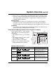
About The Keypads (cont’d) ARMED 1 OFF 2 AWAY 3 STAY ARMED 1 OFF 2 AWAY 3 STAY READY 4 MAX 5 TEST 6 BYPASS READY 4 MAX 5 TEST 6 BYPASS 8 CODE 9 CHIME 7 INSTANT 8 CODE 9 CHIME 0 # READY 0 # 6150-00-001-V0 READY 6160-00-001-V0 7 INSTANT Standard Alpha Display Keypad ARMED 1 OFF 2 AWAY 3 STAY RECORD VOLUME READY 4 MAX 5 TEST 6 BYPASS MESSAGE 7 INSTANT 8 CODE 9 CHIME READY 0 MIC STATUS VOICE PLAY # FUNCTION 6160V-00-006-V0 Standard Fixe
About The Keypads (Cont’d) FIXED-WORD DISPLAY KEYPAD AWAY: STAY: NIGHT-STAY: INSTANT: BYPASS: NOT READY: NO AC: AC: CHIME: BAT: ALARM: CHECK: FIRE: CANCELED: – 10 – All burglary zones, interior and perimeter, are armed. Perimeter burglary zones, such as protected windows and doors, are armed. NIGHT and STAY indicators both light when perimeter burglary zones plus pre-selected interior zones (set by the installer) are armed.
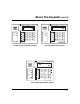
Functions of the Keypads 2 1 3 4 20 19 18 17 16 5 1 ARMED READY OFF 2 AWAY RECORD VOLUME 4 5 MAX TEST 3 STAY PLAY 6 BYPASS 6 7 8 9 7 MESSAGE MIC 14 13 INSTANT 8 READY 0 CODE 9 CHIME # STATUS VOICE 12 11 10 FUNCTION 6160V-00-007-V0 15 Voice-capable 2-line Alpha keypad (shown with flip-down front door removed) IMPORTANT! • Match the numerical callouts in the above graphic with the corresponding number on the following pages for a description of usage.
Functions of the Keypads (cont’d) [PLAY] On Voice keypads, used in conjunction with the FUNCTION and VOICE keys to play the recorded message. NOTE: The functions printed directly on the keys indicate their primary purpose; the functions printed under some of the keys (shown in brackets under the respective key), indicate their alternate or secondary purpose. 1.
Functions of the Keypads (cont’d) 11. # This key can be used for "Quick Arming" of the system without use of a security code (if programmed). [FUNCTION] On Voice keypads, enables the desired voice or volume function. 12. 0 [VOICE] On Voice keypads, enables the RECORD, VOLUME and PLAY functions. 13. ∗ READY Used to display all open protection zones. [STATUS] On Voice keypads, a momentary press of the STATUS key annunciates the current system status.
Entry/Exit Delays Entry Delay Entry Delays give you time to disarm the system when you re-enter through the designated entrance door. There are two entry delays (if programmed). The first is for your primary entrance and the second can be used for a secondary entrance, where a longer delay is required to walk to the keypad to disarm the system. You must disarm the system before the entry delay period ends, or an alarm will occur.
Entry/Exit Delays (cont’d) Exit Alarms Exit Error Conditions Whenever you arm the system, the exit delay begins. If an entry/exit door or interior zone is faulted before exit delay expires and remains faulted (e.g., exit door left open), the system sounds an alarm and starts the entry delay timer. If you disarm the system before the entry delay ends, the alarm sound stops and the message "ALARM CANCELED " or "CA" is displayed on the keypad, along with a zone number indicating the faulted zone.
Checking For Open Zones Using the [∗ ∗] Key to Display and Announce System Status Before arming your system, all protected doors, windows and other protection zones must be closed or bypassed; otherwise the keypad will display a "Not Ready" message. Use the READY key to display all faulted zones, making it easier for you to identify and secure any open zone. 1. Press [✱] (do not enter code first) to display faulted zones. 2. Secure or bypass the zones displayed.
Arming the System STAY Mode: Arms Perimeter Only, Entry Delay On • Used when you want to arm the system with persons staying inside (or if you have pets that are moving throughout the premises). • The perimeter sensors are armed, but interior sensors are left disarmed. • Exit delay begins (you can leave through the entry/exit door, if desired). • An alarm sounds if any protected window or non-entry/exit door is opened. • You may otherwise move freely within the premises.
Arming the System (cont’d) Arming Commands Before arming, close all perimeter doors and windows and make sure the Ready to Arm message is displayed.
Arming the System (cont’d) Single Button Arming The “A”, “B”, “C”, and/or “D” keys on your keypad may have been programmed for single-button arming. Note that while it is not necessary to use a security code for arming (by using the Quick Arm method described previously), a security code must always be used when manually disarming the system.
(if programmed) Keyswitch Using the Keyswitch Your system may be equipped with a keyswitch for use when arming and disarming. Red and green lights on the keyswitch plate indicate the status of your system as follows: Green Light: Lights when the system is disarmed and ready to be armed (no open zones). If the system is disarmed and the green light is off, it indicates the system is not ready (one or more zones are open). Red Light: Lights or flashes when system is armed in AWAY or STAY mode.
Disarming and Silencing Alarms Using the [OFF] key The OFF key is used to disarm the system, silence alarm and trouble sounds, and clear alarm memories. IMPORTANT: If you return and the main burglary sounder is on, DO NOT ENTER, but CONTACT THE POLICE from a nearby safe location. If you return after an alarm has occurred and the main sounder has shut itself off, the keypad will beep rapidly upon your entering, indicating that an alarm has occurred during your absence.
Bypassing Protection Zones Using the BYPASS Key Use this key when you want to arm your system with one or more zones intentionally unprotected. The system must be disarmed first. Vent Zones: Your system may have certain windows set as “vent” zones, which are automatically bypassed if left open when arming the system (you do not need to manually bypass them). However, if a vent zone window is closed after arming, it becomes protected and will cause an alarm if opened again while the system is armed.
Bypassing Protection Zones (cont’d) Quick Bypass If programmed, "Quick Bypass" allows you to easily bypass all open (faulted) zones without having to enter zone numbers individually. This feature is useful if, for example, you routinely leave certain windows open when arming at night. + 1. 6 BYPASS + [#] (Security Code) In a few moments, all open zones will be displayed and automatically bypassed.
Chime Mode Using the Chime Mode CHIME mode alerts you to the opening of a perimeter door or window while the system is disarmed. When Chime mode is activated: • Three tones sound at the keypad whenever a perimeter door or window is opened. • Interior zones do not produce a tone when they are faulted. • Pressing the READY key will display the open protection points. • Chime mode can be used only while the system is disarmed.
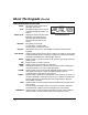
Date and Time Viewing the Current Date and Time The master users can view the system time and date setting on an alpha keypad. Other users can view the date/time if a function key has been programmed to do so. Alpha Display: + [#] + [6] [3] (Master Code) OR, Press the function key (A, B, C, or D) for viewing current date and time, if programmed. A typical time/date display is shown. The display will remain on for about 30 seconds or until a key is pressed.
Panic Keys Using Panic Keys Your system may have been programmed to use special keys to manually activate emergency (panic) functions as follows: This Function Silent Alarm Sends This Signal* silent alarm With This Sounding… no audible alarm; displays, “Press [∗] to show faults,” indicating that a silent alarm has been initiated. Audible Alarm audible alarm a loud, steady alarm at keypad(s) and at any external sounders that may be connected.
Macro Key Programming & Usage About Macro Keys The “A”, “B”, “C” or “D” keys can be used to automatically activate a series of commands of up to 16 keystrokes, if programmed for this function. These keystrokes, as a group, are called “macros” and are stored in the system's memory. • Typical macro functions can include: - Arming sequences: STAY, NIGHT-STAY, INSTANT, or AWAY - Bypassing particular zone(s) - Activating relay(s) for turning on (or off) lights, fans, etc.
Macro Key Programming & Usage (cont’d) The keypad beeps to acknowledge your input and displays the command you entered (followed by “F”). 4. Enter the next command, followed by press/holding the “D” key for at least two seconds. The keypad beeps and displays the keystrokes entered so far. 5. Repeat until all the desired commands (up to 16 characters including the “F”s) have been entered. Be sure to check your keystrokes before continuing. If you made a mistake, you must start over. 6.
Using Device Commands About Device Commands Your system may be set up so that it can control certain lights or other devices. • Some devices may be automatically turned on or off by the system. • You may be able to override automatically controlled devices using the commands described below. • Some devices can be manually turned on or off using the commands described below. • See your installer for a list of devices that may be set up for your system.
Paging Feature About Automatic Paging Your system may be set up to automatically send messages to several pagers (4 pagers for VISTA-20P Series, 2 pagers for VISTA-15P Series) as certain conditions occur in your system. • The following events can be programmed by your installer to be sent to the pagers: arming and disarming†, alarms, and trouble conditions.
Paging Feature (cont’d) About Manual Paging Your system may be set up so you can manually send a message to up to four (VISTA20P Series) or two (VISTA-15P Series) pagers. • Your installer programs the paging function key and the pager phone numbers. • Pressing the paging keys sends the message 999–9999 to the selected pager. • This message could mean “call home”, “call your office”, or any other prearranged meaning.
Security Codes & Authority Levels About Security Codes Your installer assigned a master code that is used to perform all system functions. In addition, other security codes can be assigned for use by other users (VISTA-20P Series provides 47 additional codes; VISTA-15P Series provides 31 additional codes). • Only the System Master and Partition Master can assign security codes to users.
Security Codes & Authority Levels (cont’d) How to Assign Security Codes and User Attributes The following lists the various command strings for adding security codes and attributes. Refer to the User Setup chart at the back of this manual for factory defaults of user attributes and to keep a record of user programming. NOTE: Partition Master codes (VISTA-20P Series only) apply only to those user numbers previously assigned (by the system master/installer) to the partition master’s partition.
Accessing Other Partitions (VISTA-20P) About Accessing Partitions (GOTO Command and Multi-Partition Arming) Each keypad is assigned a default partition for display purposes, and will show only that partition's information. • If the user is authorized, a keypad in one partition can be used to perform system functions in the other partition by using the GOTO command. Refer to the GOTO section. • If the user is authorized, that user can arm other partitions. Refer to the MultiPartition Arming section.
Accessing Other Partitions (cont’d) Using the GoTo Command (VISTA-20P) If the user is authorized, a keypad in one partition can be used to perform system functions in the other partition by using the GOTO command. • You must use an Alpha keypad to access another partition. • Keypads automatically return to their original partition after 30 seconds with no keypad activity. + [∗] + partition number (0,1,2,3) 1.
Accessing Other Partitions (cont’d) Common Zone Operation (VISTA-20P) Ask your installer if a "common zone" was assigned. If so, check this box Your system may have been set up to use a common zone, which is an area shared by users of both partitions, such as a foyer or lobby. If so, please note the following: • The common zone will sound and report alarms only when both partitions are armed. If only one partition is armed, the system ignores faults on the common zone.
Scheduling About Scheduling The system provides end-user schedules (programmable by master/installer only), which can control various types of events. • Each schedule causes a defined event to start and stop (when appropriate) at a specified time. • Schedules can be set to automatically repeat at various intervals. • Schedules can be set for random starting, if desired. • VISTA-20P Series provides up to 16 user schedules. • VISTA-15P Series provides up to 4 user schedules.
Scheduling (cont’d) 5. For event number “02,” enter the access group number. Otherwise, this prompt is skipped. Press [∗] to continue to the “Start” prompt below. 6. For event numbers “03-07,” enter the partition number to be armed or disarmed. 0 = arm all; 1 = partition 1; 2 = partition 2; 3 = arm common Otherwise, this prompt is skipped. Press [∗] to continue to the “Start” prompt. 7. Enter the event’s start time and days of week.
Event Logging Procedures About Event Logging The system records various events in a history log, which can be viewed by the master user on an Alpha Display keypad. • The Event Log holds up to 100 (VISTA-20P Series) or 50 (VISTA-15P Series) events. • Events are displayed in chronological order, from most recent to oldest. • When the log is full, the oldest event is replaced by the logging of any new event. Viewing the Event Log 1.
Event Logging Procedures (cont’d) Code Definition 143 Alarm, Expansion Module 145 ECP Module cover tamper 146 Silent Burglary 150 Alarm, 24-Hour Auxiliary/Monitor zone 162 Carbon Monoxide 301 AC Power 302 Low System Battery/Battery Test Fail 305 System Reset (Log only) 321 Bell/Siren Trouble 333 Trouble, Expansion Mod.
Testing the System About Testing the System Using the Test mode allows each protection point to be checked for proper operation. Testing should be conducted weekly to ensure proper operation. • The keypad sounds a single beep about every 30 seconds as a reminder that the system is in the Test mode. • Alarm messages are not sent to your Central Station while Test mode is on. Alpha Displays: 1. Disarm the system and close all protected windows, doors, etc.
Trouble Conditions "Check" and "Battery" Displays The word CHECK on the keypad's display, accompanied by a "beeping" at the keypad, indicates a trouble condition in the system. To silence the beeping for these conditions, press any key. 1. A display of "CHECK" and one or more zone numbers indicates that a problem exists with the displayed zone(s) and requires your attention. Determine if the zone(s) displayed are intact and make them so if they are not.
Trouble Conditions (cont’d) Words or letters in parentheses ( ) are those that are displayed on Fixed-Word Display keypads. Other Trouble Displays * Any “beeping” that accompanies a trouble display can be stopped by depressing any key on the keypad or by entering an OFF sequence (code + OFF) COMM. FAILURE (or FC) Indicates that a failure has occurred in the telephone communication portion of your system. CALL FOR SERVICE. SYSTEM LO BAT (or BAT with no zone No.
Trouble Conditions (cont’d) Other Trouble Displays (Continued) AC LOSS (or NO AC) The system is operating on battery power Busy-Standby (or dI) If this message remains displayed for more than 1 minute, system is disabled. CALL FOR SERVICE. OPEN CIRCUIT (or OC) The keypad is not receiving signals from the control. CALL FOR SERVICE. Long Rng Trbl (or bF) If part of your system, back-up Long Range Radio communication has failed. CALL FOR SERVICE.
Maintaining Your System Taking Care of Your System The components of your security system are designed to be as maintenance-free as possible. However, to make sure that your system is in reliable working condition, do the following: 1. Test your system weekly. 2. Test your system after any alarm occurs.
Fire Alarm System THIS SECTION APPLIES ONLY TO RESIDENTIAL SYSTEMS General Your fire alarm system (if installed) is on 24 hours a day, for continuous protection. In the event of an emergency, the strategically located smoke and heat detectors will sound their alarms and automatically send signals to your system, triggering a loud, interrupted pulsed sound* from the Keypad(s) and any external sounders.
Fire Alarm System (cont’d) THIS SECTION APPLIES ONLY TO RESIDENTIAL SYSTEMS Manually 1. Should you become aware of a fire emergency before your smoke or heat detectors sense the problem, go to your nearest keypad and Initiating manually initiate an alarm by pressing the panic key assigned for a Fire Alarm FIRE emergency for 2 seconds (see below). If a key pair has been assigned for fire, press both keys at the same time. See the Using the Panic Keys section below for further details. 2.
Fire Alarm System (cont’d) THIS SECTION APPLIES ONLY TO RESIDENTIAL SYSTEMS National Fire Protection Association Recommendations on Smoke Detectors With regard to the number and placement of smoke/heat detectors, we subscribe to the recommendations contained in the National Fire Protection Association's National Fire Alarm Code (NFPA 72) noted below.
Fire Alarm System (cont’d) THIS SECTION APPLIES ONLY TO RESIDENTIAL SYSTEMS Emergency Evacuation PORCH M ET OO OS DR E CL B M OM OO TH RO DR D BA E B BE 2ND FLOOR EN CH KIT BACK DOOR OM RO D BE M OO TH DR BA E B 1ST FLOOR • • BACK • FRONT Establish and regularly practice a plan of escape in the event of fire. The following steps are recommended by the National Fire Protection Association: 1.
Quick Guide to Basic System Functions FUNCTION PROCEDURE COMMENTS Check Zones Press READY key. View faulted zones when system not ready. Arm System Enter code. Press arming key desired: Arms system in mode selected. (AWAY, STAY, NIGHT-STAY, MAXIMUM, INSTANT) Quick Arm (if programmed) Press #. Press arming key desired: (AWAY, STAY, MAXIMUM, INSTANT) Arms system in mode selected, quickly and without use of a code. Bypass Zone(s) Enter code. Press BYPASS [6] key.
Summary of Audible/Visual Notifications Fixed-Word Display Keypads SOUND CAUSE LOUD, FIRE ALARM INTERRUPTED* Keypad & Ext. DISPLAY FIRE is displayed; zone number of zone in alarm is displayed. If a fire alarm is manually activated, zone number 95 will be displayed. LOUD, CONTINUOUS* Keypad & Ext. BURGLARY/AUDIBLE EMERGENCY ALARM ALARM is displayed. Zone number of zone in alarm is also displayed. ONE SHORT BEEP (not repeated) Keypad only a. SYSTEM DISARM b. SYSTEM ARMING ATTEMPT WITH AN OPEN ZONE.
Summary of A/V Notifications (cont’d) Alpha Display Keypads SOUND CAUSE DISPLAY LOUD, FIRE ALARM. INTERRUPTED* Keypad & Ext. FIRE is displayed; descriptor of zone in alarm is displayed. If a fire alarm is manually activated, zone number 95 will be displayed. LOUD, CONTINUOUS* Keypad & Ext. BURGLARY/AUDIBLE EMERGENCY ALARM. ALARM is displayed. If programmed, descriptor of zone in alarm is also displayed ONE SHORT BEEP (not repeated) Keypad only a. SYSTEM DISARM. a.
Regulatory Statements and Warnings “FEDERAL COMMUNICATIONS COMMISSION (FCC) Part 15 STATEMENT” This equipment has been tested to FCC requirements and has been found acceptable for use. The FCC requires the following statement for your information: This equipment generates and uses radio frequency energy and if not installed and used properly, that is, in strict accordance with the manufacturer’s instructions, may cause interference to radio and television reception.
Regulatory Statements (cont’d) Industry Canada (continued) Users should ensure for their own protection that the electrical ground connections of the power utility, telephone lines and internal metallic water pipe system, if present, are connected together, This precaution may be particularly important in rural areas. Caution: Users should not attempt to make such connections themselves but should contact appropriate electric inspection authority, or electrician, as appropriate.
System Features Log Features Comments Exit Delay Part. 1: Part. 2*: Entry Delay 1 Part. 1: Part. 2*: Entry Delay 2 Part. 1: Part.
System Features Log (cont’d) User Setup The following chart will help keep track of system users. Copies should be distributed to the partition† 1 and partition† 2 (if applicable) masters for their records. To program a user attribute: Enter system/partition* master code + [8] + user no. + “#” command listed in column heading. User No. User Name 01 02 03 04 05 06 07 08 09 10 11 12 13 14 15 16 17 18 19 20 21 22 23 24 25 26 27 28 29 30 31 32 installer system master partition 1 master User’s Part(s).
System Features Log (cont’d) User Setup (cont’d) Enter system/partition master code + [8] + user no. + “#” command listed in column heading. User No.* User Name 33 34 35 36 37 38 39 40 41 42 43 44 45 46 47 48 49 partition 2 master (system master only) Security Code Auth. Level [#] [3] + part(s) + [#] enter new code [#] [1] + level User’s Part(s). (2) (2) (2) (2) (2) (2) (2) (2) (2) (2) (2) (2) (2) (2) (2) (2) (2) Access Group RF Zone Number Pager on/off [#] [2] + group [#] [4] + zone no.
System Features Log (cont’d) Schedules*: master code + [#] + [6] [4] No. Event Device No. (see list below) for “01” events: Group No.
OWNER’S INSURANCE PREMIUM CREDIT REQUEST This form should be completed and forwarded to your homeowner’s insurance carrier for possible premium credit. A. GENERAL INFORMATION: Insured’s Name and Address: Insurance Company: Policy No.: VISTA-20P / VISTA-15P Other _____________________________________________________ (circle the appropriate model number) Type of Alarm: Burglary Fire Installed by: Both Serviced by: Name Name Address Address B.
OWNER’S INSURANCE PREMIUM CREDIT REQUEST (cont.) E. SMOKE DETECTOR LOCATIONS Furnace Room Kitchen Bedrooms Attic Basement Living Room Dining Room Hall Basement Door Rear Door All Exterior Doors All windows Interior locations F. BURGLARY DETECTING DEVICE LOCATIONS: Front Door st 1 Floor Windows All Accessible Openings, Including Skylights, Air Conditioners and Vents G.
– Notes – – 61 –
– Notes – – 62 –
LIMITATIONS OF THIS SYSTEM WARNING! THE LIMITATIONS OF THIS ALARM SYSTEM While this system is an advanced design security system, it does not offer guaranteed protection against burglary or other emergency. Any alarm system, whether commercial or residential, is subject to compromise or failure to warn for a variety of reasons. For example: • Intruders may gain access through unprotected openings or have the technical sophistication to bypass an alarm sensor or disconnect an alarm warning device.
ONE YEAR LIMITED WARRANTY Honeywell International Inc., acting through its Security & Custom Electronics business ("Seller"), 2 Corporate Center Drive, Melville, NY 11747, warrants its security equipment (the "product") to be free from defects in materials and workmanship for one year from date of original purchase, under normal use and service.