MAXPRO-Net Crosspoint Matrix Video Switching System Operator’s Manual HMXMU001056 - March 2005 - Rev.
Rev.
SOFTWARE LICENSE AGREEMENT Honeywell International Inc. 165 Eileen Way, Syosset, NY 11791 . You should carefully read the following terms and conditions. If you do not consent to be bound by this License Agreement, you must promptly return the unopened package to the person from whom you purchased it within fifteen (15) days from date of purchase and your money will be refunded to you by that person.
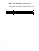
PATENT AND TRADEMARK INFORMATION Portions of MAX-1000, its software, and its components are protected by one or more of the following patents or trademarks. Australian Patent US Patent British Patents Singaporean Patent Australian Trademarks US Trademark Rev.
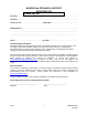
MAXPRO-Net TECHNICAL SUPPORT REGISTRATION License Key No: Site name: .......................................................................................................................................................... Company:.......................................................................................................................................................... Contact person: .................................................. Position/title:.........................................
MAXPRO-Net TECHNICAL SUPPORT "BEFORE YOU CONTACT TECHNICAL SUPPORT" License Key No: Before you call requesting technical support you should obtain the following information. This will save you time and money and allow our support staff to attend to your difficulties promptly. Have you registered the site? As discussed on the registration form, you must have pre-registered your new MAXPRO-Net software license PRIOR to requesting our technical support services.
TABLE OF CONTENTS CHAPTER 1: OVERVIEW .......................................................................................................................1-1 1.1 GENERAL DESCRIPTION.......................................................................................................... 1-1 1.2 SYSTEM KEYBOARDS .............................................................................................................. 1-2 1.3 OTHER EQUIPMENT ........................................................
TABLE OF CONTENTS, CONTINUED 3.7 CHANGING THE DWELL PERIOD........................................................................................... 3-11 3.8 INCREASING THE DWELL FOR ONE CAMERA ..................................................................... 3-13 CHAPTER 4: USING MACROS..............................................................................................................4-1 4.1 WHAT IS A MACRO? ...............................................................................
TABLE OF CONTENTS, CONTINUED CHAPTER 7: THE TEXT CHANNEL MENU SYSTEM............................................................................7-1 7.1 WHAT IS THE TEXT CHANNEL MENU SYSTEM? .................................................................... 7-1 7.1.1 Accessing the MENU SYSTEM..................................................................................... 7-1 7.1.2 Exiting the MENU SYSTEM ..........................................................................................
TABLE OF CONTENTS, CONTINUED CHAPTER 10: TROUBLESHOOTING..................................................................................................10-1 10.1 SELECTING A CAMERA .......................................................................................................... 10-1 LIST OF TABLES Table 3.1: Entry Positions In Scan Sequence 20......................................................................................3-7 Table 3.
CHAPTER 1: OVERVIEW 1.1 GENERAL DESCRIPTION MAXPRO-Net combines custom designed software with a high performing Windows 2003 Server resulting in Honeywell's Turn Key Centralized Management Console Server. MAXPRO-Net is designed for system configuration, system management and system monitoring of Honeywell's crosspoint matrix video switchers. Using a system keyboard, an operator can select various cameras for display on the available video display monitors.
1.2 SYSTEM KEYBOARDS The system keyboard, along with text message information (available via the video display monitors), is used by the operator to control the MAXPRO-Net Crosspoint Matrix Video Switcher. Depending on the size of the video system, there could be up to thirty-two (32) keyboards connected to the system. They can all operate the system at the same time and still be totally independent of each other. There are two types of keyboard available. 1. The HEGS5300 enhanced keyboard. 2.
1.5 CONVENTIONS USED IN THIS MANUAL During the course of this manual, icons and examples are used, wherever possible, to help illustrate certain points. 1.5.1 Keystrokes Actual keys, used on the keyboard to perform certain functions, will be represented in our examples, by icons of the respective keys. 1.6.2 • for example, • or .. represents the '0' key, .. represents the 'Alarm Clear' key. Numerical Range The video system consists of numerous video input and output channels.
1.6.4 Monitor messages Every monitor can display, in its text message window, the current time/date, camera description and operator name. These parameters would be defined during the setting up of the system's configuration. In addition to these, other messages that report alarm conditions or system status will also be displayed. These special messages will also appear in the text message window, usually above the normal text messages mentioned earlier.
CHAPTER 2: GETTING STARTED 2.1 ENTERING YOUR SELECTION NUMBERS HOW AND WHY? For nearly all keyboard operations discussed in this manual, an associated numeric entry must be made. For example, when selecting a camera or setting the dwell for a scan sequence. The required number is typed in, using the SELECTION PAD on the keyboard. When the number entered is shorter in length than expected (that is, less digits than expected), then the key must be pressed to indicate that the number entered is complete.
2.2 SELECTING A MONITOR NOTE: To change the current picture on a video display monitor, a monitor must first be selected. Press the key followed by the monitor number required. • for example, • .. selects monitor 6 (for a system having ten or or more possible monitors to select from). .. selects monitor 3, The monitor description text will now be replaced by the name of your keyboard, for example: NOTE: As an operator, your own name may appear instead.
2.3 SELECTING A CAMERA NOTE: A monitor must be selected first. Press the key followed by the number of the camera required. • for example, • or or more possible cameras). .. selects camera 25, .. selects camera 1 (for a system having ten The monitor should now be displaying the new camera selected. The camera description text should also be displayed. NOTE: It is possible that the camera selected is not available.
2.4 CONTROLLING A CAMERA PTZ To operate a camera PTZ site, the following must first be true. • you must currently be selecting a monitor, • the monitor must be displaying the desired camera, • the desired camera must have PTZ equipment fitted. Camera pan, tilt, focus, and zoom control functions are detailed below. They are the same on both the RD-500 and RD-530 keyboards. PAN LEFT .. by pushing (and holding) the joystick towards the Left. Releasing the joystick will halt the pan function.
2.4.1 Other PTZ functions The following PTZ functions may be available as well provided the keyboard being used supports the function. Refer to your specific keyboard user manual. • ZOOM IN .. by pressing (and holding) the will halt the Zoom function. • ZOOM OUT .. by pressing (and holding) the will halt the Zoom function. • FOCUS FAR .. by pressing (and holding) the will halt the Focus function. • FOCUS NEAR .. by pressing (and holding) the key will halt the Focus function. • IRIS OPEN ..
2.5 SELECTING A VCR NOTE: A monitor must be selected first. Press the key, followed by the VCR number. • for example, • or selects VCR 10, selects VCR 4. The monitor should now be displaying the video from the output of the VCR selected. The VCR description text should also be displayed on the monitor. 2.6 CONTROLLING A VCR FROM THE KEYBOARD , Control of VCRs may be denied for some operators The VCR control functions are listed below. They are the same for both keyboards.
2.6 CONTROLLING A VCR FROM THE KEYBOARD, CONTINUED .. to rewind the tape. .. to fast-forward the tape. .. half speed play. For some VCR's this is shuttle mode. .. to pause playback (still-frame). .. to begin recording. .. to eject the tape. .. to temporarily hide the text display on the monitor. When VCRs with SMARTEXT are played back, the concealed text can be displayed on the monitor again. NOTE: Some functions of the VCR may not be available for your system. Rev.
2.7 RECORDING A CAMERA To record a camera onto a VCR: • you must first select a monitor, • then the required VCR must be selected onto the monitor, Next press the key. The prompt: appears on the monitor. Now, make your camera selection, exactly as if you were selecting the camera directly on the monitor. • for example, as the video source for the current VCR. • or video source for the current VCR. .. selects camera 15 ..
2.8 AUXILIARY DEVICES AND MULTIPLEXERS Various other types of devices such as video multiplexers, or motion detectors and video printers can also be selected. To select a device; • a monitor must first be selected;. Press the desired device type key followed by the number of the device required. • for example, (5), • or .. selects the multiplexer device number .. selects an auxiliary device number (10). The monitor should now be displaying the video from the output of the device selected.
NOTES: Rev.
CHAPTER 3: USING SCAN SEQUENCES 3.1 WHAT IS A SCAN SEQUENCE? A Scan Sequence is a list of camera selections. This camera list, or scan sequence, is used to automatically display every camera in the sequence on a specific monitor. Each camera selection will remain displayed for a specified duration defined by the 'Dwell Time' setting of each scan sequence. When the scan sequence reaches its end, it wraps back around and starts again, creating an endless sequence of pre-defined camera selections.
3.2 STARTING A SCAN SEQUENCE Firstly, a monitor must be selected. Press the key, followed by the scan sequence number required. Valid scan sequence numbers are (01 Ù 99). • for example, starts it running. • or .. selects scan sequence 21 and .. selects scan sequence 5 and starts it running. The key is required because the valid range is (01 Ù 99). The monitor will now be displaying cameras from the scan sequence list. The following message would be briefly displayed.
3.3 HALTING A SCAN SEQUENCE To halt a scan sequence, the operator must have selected the monitor running that scan sequence. When the key is pressed, the message: will be displayed. The last camera selection made by the scan sequence will remain displayed on the monitor. To restart a previously halted scan sequence, press the key followed by the key. A number is not required. • for example, this monitor. ..
3.4 PAUSING A SCAN SEQUENCE Sometimes, it is necessary to temporarily pause the scan sequence. This allows you to manually step forwards and backwards through the scan sequence. To pause a scan sequence, you must already be selecting a monitor that is running the desired scan sequence. Press the key. This message will be displayed: The current camera selection made by the scan sequence will remain displayed on the monitor.
3.5 MAKING A NEW SCAN SEQUENCE , Access denied to some operators To make a new scan sequence, a monitor must first be selected. Select the NEW scan sequence. • for example, starts it scanning. Press the The message .. selects scan sequence 20, and key to first pause the scan sequence. Now, press the key. will be displayed briefly. You are now in 'SET SCAN' mode.
3.5 MAKING A NEW SCAN SEQUENCE, CONTINUED Before the next camera can be selected, we have to make room in the sequence list. Press the key to insert a new entry into the scan sequence. Press to this NEW ENTRY. to move Now the next camera for this sequence can be selected. • for example, the second camera in scan sequence 20. .. selects camera number 12 as The entire procedure can be summarized as follows: • .. selects scan sequence 20, and starts it scanning. • pauses scan sequence 20.
3.5 MAKING A NEW SCAN SEQUENCE, CONTINUED • creates another new entry for scan sequence 20. • moves you to the third entry of scan sequence 20. • .. selects camera number 29 as the third entry of scan sequence 20. By now, the following cameras are present in scan sequence 20: Entry position in Scan Sequence 1 2 3 Camera No. 2 12 29 Table 3.1: Entry Positions In Scan Sequence 20 Continue until all the desired cameras in the scan sequence have been entered.
3.6 EDITING A SCAN SEQUENCE , Access denied to some operators To edit a scan sequence it is necessary for the desired sequence to be selected to the operator's monitor. for example, .. selects scan sequence 20, and starts it scanning. Press the key to pause the scan sequence. Now, press the key. The message: will be displayed. The 'SET SCAN' mode is now enabled and the operator can begin to edit the scan sequence. Use the entry list.
3.6.1 Overwrite With A New Camera Selection, Continued Simply use the following keys: or keys to move to the second entry position, and press the • selects camera number 25 as the second entry in scan sequence 20. Camera number 12 is now overwritten by the camera number 25. Entry position in Scan Sequence 1 2 3 4 5 Camera No. 2 25 29 14 17 Table 3.3: Entry Positions In Scan Sequence 20 After Overwriting. 3.6.
3.6.3 Insert A New Camera Selection Pressing the key will insert a new selection entry into the scan sequence at the current entry position. All entries following this position will be shifted up once, to make room. The following 3 tables illustrate what happens when camera number 10 is inserted into entry position (3) of the scan sequence. Use the or keys to move to the third entry position of the scan sequence. Entry position in Scan Sequence 1 2 3 4 5 Camera No.
3.6.3 Insert A New Camera Selection. Continued To start scan sequence 20 running, press the key once. The message: will be displayed briefly. Scan sequence 20 is now running. CAUTION: Some scan sequences cannot be changed as they have been predefined and locked at system commissioning. 3.7 CHANGING THE DWELL PERIOD , Access denied to some operators To edit a dwell period it is necessary for the desired scan sequence to be running on the monitor. • for example, starts it scanning.
3.7 CHANGING THE DWELL PERIOD, CONTINUED Use the key to move backwards in the scan sequence. Continue pressing the key until the beginning of the scan sequence list is reached (that is, before Entry (1)). Entry position in Scan Sequence 0 1 2 3 4 5 Camera No. dwell period 2 25 12 29 14 Current entry position selected * Table 3.10: Using The Key To Move To Entry (0). The message: will be displayed briefly, together with the current dwell setting (in seconds).
3.8 INCREASING THE DWELL FOR ONE CAMERA As there is only one Dwell Period setting for the entire scan sequence camera selection list, the method of varying the dwell period for one specific camera is to enter that camera selection two or more times (consecutively) into the scan sequence list. This method allows individual cameras to remain displayed for two, three, or more multiples of the current dwell period. Rev.
NOTES: Rev.
CHAPTER 4: USING MACROS 4.1 WHAT IS A MACRO? A MACRO is a stored recording of a series of keystrokes made by an operator on a keyboard. This recording can be PLAYED BACK by the operator whenever required. It will mimic the operator by automatically making those same keystroke actions again. Macros can be used to automate the system in three ways; 4.1.
4.1.3 Automated Control The MAXPRO-Net Crosspoint Maxtrix Video Switching System can be configured to control a variety of equipment other than cameras and monitors. The keyboard actions used to manually control this auxiliary equipment can also be recorded in a macro for later play back for automated control of the system. Selecting cameras to video recorders, activating record, turning lighting on, or opening door latches and boom gates could all be included in one automated control macro.
4.2 EXECUTING A MACRO, CONTINUED Although a macro can be executed by any operator from any keyboard, it can only be executed by one person at a time. If the following message; is displayed, then you must wait until the operator using that macro is finished. NOTE: If a macro sequence is executed without having a monitor selected, no messages will be displayed. 4.3 MAKE A NEW MACRO , Access denied to some operators Press the key followed by the key. The prompt: will be displayed.
4.3 MAKE A NEW MACRO, CONTINUED The system will now begin recording operator keyboard actions. These may be recorded in a REALTIME mode whereupon running of the macro the operator actions will be played back with the same timing with which they were recorded, or in AUTO-TIMING mode whereupon operator actions will be played back automatically timed. The recording mode may be toggled during recording by pressing the key. The prompt: or will then be displayed briefly to indicate the current mode.
4.4 DELETE A MACRO , Access denied to some operators A macro must be deleted before it can be redefined. Press the by the key followed key. The prompt: will be displayed. Now, select the two-digit macro number you wish to delete. Valid MACRO's are (00 Ù 99). • for example, • or .. deletes macro (65). .. deletes macro (00). The message prompt; will then be displayed briefly. Your macro is now deleted. It is ready to be defined again. 4.4 CAN I EDIT A MACRO? NO.
NOTES: Rev.
CHAPTER 5: MANAGING ALARMS 5.1 WHAT ARE ALARMS? ALARMS are usually external inputs to the crosspoint matrix video switching system. These inputs are watched continuously by the equipment. If a change in alarm state occurs on an alarm input, the system operators can be prompted immediately and automatic selection of cameras and VCRs, and so on, can also occur. The automatic action taken for any given alarm input is programmed at commissioning and therefore cannot be changed by an operator.
5.2 EXTERNAL ALARM INPUTS External alarm inputs are usually hard wired into the subrack equipment. They include perimeter security alarms, PIR movement detectors, intercom alarms, door state alarms, and so on. External alarms are sometimes monitored by a separate security system and communicated back to the MAXPRO-Net system for action. 5.3 CAMERA FAIL ALARMS In some video systems, the cameras are automatically monitored to check for camera malfunction and/or cut-cabling, and so on.
5.5 PTZ SITE TAMPER ALARMS To protect a camera PTZ site from unauthorized access, the tamper alarm input would be used. A tamper alarm is LATCHING, so once activated, it can only be cleared from the keyboard by an operator. 5.6 VCR ALARMS VCR alarms are commonly used to detect END OF TAPE or NO RECORD status conditions and report these to the operator. The VCR alarm would be cleared automatically by rectifying the reported condition. VCR alarms can also be cleared from a keyboard. 5.
5.9 STEPPING THROUGH THE ALARM STACK CAUTION: You must currently be selecting the monitor that is displaying the flashing alarm messages. On the HEGS5300 enhanced keyboard, pressing the key will manually force the alarm stack to cycle to the next active alarm. Immediately, the next alarm will be displayed on the monitor. The alarm stack will still automatically cycle after the usual pause period. 5.
5.10 CLEARING AN ALARM, CONTINUED key while the selected monitor is not displaying an active alarm Pressing the will display the message prompt; even if there are still active alarms displayed on another monitor. Rev.
NOTES: Rev.
CHAPTER 6: OTHER KEYBOARD FUNCTIONS 6.1 FAST CAMERA SELECTION To scroll quickly between the available cameras, the following keys may be used; • Press the key to select the NEXT camera. • Press the key to select the PREVIOUS camera. The selection of cameras with these keys is dependent on the current monitor being used and the access level of the operator. NOTE: These keys also apply to VCRs and other devices. When the current selection is a VCR, the next (or previous) VCR would then be selected.
6.2 SETTING A NEW CAMERA VIEW (PTZ PRESET POSITION), CONTINUED Using the camera PTZ functions, move to the desired position of the new view. Press the key followed by the key. The message: will be displayed. Now, press the view number (0 Ù 9). A total of ten views per camera are possible from the keyboard. • for example, for this camera as view 5. • or .. stores the current PTZ position for this camera as VIEW 0 and the monitor will display the message: ..
6.3 RECALLING A CAMERA VIEW (PTZ PRESET POSITION) To recall a PTZ camera view the following must first be true. 1. you must currently be selecting a monitor, 2. the monitor must be displaying the desired camera, 3. the desired camera must have PTZ equipment fitted with VIEW (preset) capability. Press the key followed by the view number required. The range of valid views are (0 Ù 9). A total of ten views per camera PTZ site are available. • for example, • or .. selects camera view 5, ..
6.4 CAMERA PTZ FLASHBACK, CONTINUED Press the key to move to the first FLASHBACK position. This is similar to recalling a preset view, although the prior position is first remembered. The dome PTZ can be operated manually as required. key. Now your current position To go back to the prior position, press the is remembered and the prior position is recalled. The FLASHBACK feature allows two separate targets to be followed using the one high-speed dome camera.
6.5 HIDING DISPLAYED TEXT The displayed monitor text is used to identify the selected camera, present current time/date and other prompt messages. Sometimes, it is required that the displayed text be turned-off (or hidden) allowing the total picture area to be viewed. To hide the displayed text, the following must first be true. • You must currently have a monitor selected Press the key to remove the text from the monitor. You can manually control the selected PTZ camera as required.
6.7 REVEALING SMARTEXT, CONTINUED By selecting another camera or moving to another monitor, the normal monitor text display will be restored and the SMARTEXT information will again be concealed. CAUTION: SMARTEXT is only available on specific video systems that are designed to support this feature. Rev.
CHAPTER 7: THE TEXT CHANNEL MENU SYSTEM 7.1 WHAT IS THE TEXT CHANNEL MENU SYSTEM? The MAXPRO-Net generates the Menu system using the Text Lines displayed on the Monitor, which enables the Operator to perform Sign in, Sign Off, Change PIN operations. MAXPRO-Net V5.2 SIGN-ON OPERATOR 04MAR2005 11:50:29 Fig 7.1: Menu displayed on the Monitor Text Channel The Three Options of the Text Channel Menu System, 7.1.
7.2 MAKING SELECTIONS FROM THE MENU • When the Menu is selected, the First Option of the Menu ’SIGN-ON OPERATOR’ will be displayed on the Text Channel. Pulling the joystick towards you will move down the menu to the Second Option ’Sign Off Operator.’ Pushing the joystick away from you will move up the menu to First option ’Sign On Operator.’ By making several joystick actions, you can navigate to other options of the Menu.
7.3 SIGN-ON KEYBOARD OPERATORS In the MAXPRO-Net Crosspoint Matrix Video Switching System, a keyboard must have an operator identity associated with it before access to the video system is allowed. • To sign-on a new operator to the keyboard, press the key. Then, first option of the menu ’SIGN-ON OPERATOR’ will be displayed. Press Key, then Valid ‘Keyboard Operator List' is displayed.
7.3 SIGN-ON KEYBOARD OPERATORS, CONTINUED SIGN-ON CONFIRMED 04MAR2005 11:50:29 Fig 7.2: Sign On Confirmed If the keyboard is already signed-on by another operator, you should still sign-on to the system using your own operator identity. Every operator has his or her own access privileges necessary for controlling the video system. 7.4 SIGN-OFF KEYBOARD OPERATORS , Access denied to some operators.
7.5 CHANGE PIN NUMBER , Access denied to some operators To change a PIN, the operator must be signed onto the keyboard. From the main menu, highlight and select the item 'Change PIN number.' WARNING: If you do not have the correct access privileges, the message, 'ACCESS DENIED' will be flashed on the monitor. MAXPRO-Net V5.2 CHANGE PIN 04MAR2005 11:50:29 Fig 7.15: Change PIN Enter New PIN **** 04MAR2005 11:50:29 Fig 7.
7.5 CHANGE PIN NUMBER, CONTINUED Another entry window is displayed. To confirm your new PIN number, enter it a second time. Confirm New PIN and Press Enter **** 04MAR2005 11:50:29 Fig 7.16: Confirm new PIN number, again OK PIN Changed 04MAR2005 11:50:29 Fig 7.17: New PIN number OK The menu prompt 'OK PIN changed' is then displayed. CAUTION: Record your new PIN number for future reference in a safe and secure place. Rev.
CHAPTER 8: MESSAGE PROMPTS 8.1 INTRODUCTION The MAXPRO-Net Crosspoint Matrix Video Switching System creates an interactive environment for the system operators. Using the keyboard, an operator is able to communicate and control the video system. The system will also communicate with the operator using text message prompts. These are displayed on the operator's currently selected monitor.
8.2 SELECTIONS, CONTINUED Message Prompt Explanation Set source You can now enter the camera selection to be set as the new source selection of the VCR (or other device) currently on the monitor. It is not selected directly onto the monitor but to the video input of the VCR itself. Access denied Your keyboard does NOT have access to this VCR (or other device). It cannot make new video source selections for this VCR's video output channel.
8.2 SELECTIONS, CONTINUED Message Prompt LIVEUPDATE COMPLETED 8.3 Explanation This indicates that the 'live configuration update' operation to the MAXPRO-Net Server is complete. The operator can resume his control on the system. SCAN Message Prompt Explanation Not while scanning Before selecting a camera to this monitor, the current scan sequence must be halted. Invalid sequence The scan sequence requested is not valid. Try a different scan sequence number instead.
8.3 SCAN, CONTINUED Message Prompt Explanation End of tour The end of the guard tour sequence has been reached. The tour has been halted. Tour halted The guard tour sequence has been manually halted. You can now manually select cameras to the monitor. Tour paused The guard tour is now paused. You can now step manually forwards and backwards through the sequence. Set tour The guard tour is now in SET mode. It can now be edited.
8.4 PAN-TILT CONTROL Message Prompt Explanation Fixed camera This camera does NOT have any PTZ capability. Not while scanning Before controlling the PTZ camera on this monitor the current scan sequence must be halted. PTZ denied The keyboard operator does not have access to control this PTZ camera. PTZ busy Another keyboard operator is currently controlling this camera PTZ. PTZ locked All of the camera PTZ control functions have been locked. The PTZ cannot be controlled until it is unlocked.
8.4 PAN-TILT CONTROL, CONTINUED Message Prompt Explanation Set view (0-9) Enter the PTZ camera preset view number to be set (single digit). View (xx) is set A new preset view (xx) has been entered for this camera PTZ. This preset view now retains the current position of the PTZ. Set view - denied This keyboard operator does not have access to set PTZ camera preset views. No views available This keyboard operator does not have access to PTZ camera preset views. 8.
8.6 OTHER CONTROL Message Prompt Explanation CTRL config. error The PTZ (or VCR) control definition has been incorrectly configured. Control of this device is not possible until it is properly defined. Control denied This keyboard operator does not have access to control this device. Incorrect function The control function number used is not valid for this device. Device busy This device is currently being used by another operator.
8.8 GENERAL Message Prompt Explanation No alarm present You pressed the alarm clear key but there are no alarms currently displayed on this monitor. Busy-please wait The MAXPRO-Net Server is updating the disk storage files with your scan sequence, user macro or other changes. This could take several seconds before normal control of the system is restored. Busy-using PTZ Another keyboard/operator is controlling this PTZ camera. Busy-using VCR Another keyboard/operator is controlling this VCR.
Menu is busy The system MENU is already being used by another operator. Wait a while and try again. Test mode frozen The diagnostic test mode display has been frozen. The system MENU cannot be used until the diagnostic test mode is released. Wait for the service engineer to complete their testing, then try to access the system MENU again. LIC:XX_DAYS_LEFT This prompt indicates that you are running a trial version of the software.
Keyboard Fail (xx) The keyboard (xx) has failed to respond to polling commands. The data communication channel to the keyboard may be disconnected or the keyboard may have failed. Call technical support for immediate support. Network Fail #.. The networked system (#..) has failed to respond to polling commands. The data communications channel to the networked system may be disconnected or the network system may have failed. Call technical support for immediate support. Rev.
CHAPTER 9: SYSTEM FEATURES 9.1 REAL TIME CLOCK (RTC) The Real Time Clock is the current time and date. It changes every second, even while the system is turned off. The real time clock is used to display current time/date text on the monitors. The text insertion display format for the time/date is: DD/MMM/YY hh:mm.sec: for example, 31/Jan/96 23:59.01 WARNING: Not all MAXPRO-Net systems will display seconds as seconds are only supported when ENHANCED and SMARTEXT text modules are used. 9.
9.2.1 Post-Text Post text inserters are used to identify the currently selected camera and display time/date, current operator name and other system information onto the monitor. 9.2.2 Pre-text Pre-text inserters are sometimes used when cameras need to be recorded onto a dedicated video recorder. They provide identification of that camera as well as the current time/date display. Pre-text would not usually be used in the system. 9.
9.6 MONITOR ACCESS To structure the control of a large video switching system (that is, a system with several monitors physically located at different control locations) it is necessary to restrict the control access that each keyboard can have over the available monitors. Each keyboard has it's own identification number (1 Ù 32). The keyboard ID numbers are allocated to each monitor during commissioning. Only the allocated keyboards are allowed to access and select cameras on that monitor.
9.8 PRIORITIZING OPERATORS As the system can be controlled by more than one keyboard at the same time, it is sometimes possible to have a situation where a conflict of monitor access and PTZ camera control arises. The MAXPRO-Net system handles such conflicts by prioritizing all system operators. There are a hundred (0 Ù 99) possible operator priority codes. With the exception of priority code (0), the level of priority relates directly to numerical code assigned (that is, 1= highest, 99= lowest).
9.9 KEYBOARD TIME-OUT If a keyboard is left selecting a monitor and the operator does not operate the keyboard for the pre-defined time-out period, then the keyboard will be de-selected from that monitor. (The monitor can now be accessed by other keyboards). The following message will be displayed: Camera selections are now ignored until another monitor is selected. CAUTION: The operator is still signed-ON to the keyboard. 9.
9.11.2 Low level video Even though the camera's video signal if NOT lost, the camera scene is electronically monitored. If the video picture should go completely black for several seconds, then a 'LOW-LEVEL VIDEO' alarm is generated identifying that camera. Area lighting being turned OFF, the lens of the camera being covered, or the lens iris being completely closed could cause this alarm. Rev.
CHAPTER 10: TROUBLESHOOTING 10.1 SELECTING A CAMERA 1. Check that you have first selected a monitor for use. The keyboard identity or your operator name should be displayed in the text on the monitor you are currently selecting. 2. Are you using the correct number of digits for the camera selection number? Try using the key to complete your camera selection number. 3. In case your number entry is offset by a digit or two, try pressing the again to begin a new camera selection number. key 4.
Honeywell Video Systems (Head Office) 171 Eileen Way Syosset, NY 11791, USA www.honeywellvideo.com TEL+1-516-921–6704 Honeywell Security Australia Pty Ltd. Unit 5, Riverside Centre, 24-28 River Road West Parramatta, NSW 2150, Australia www.ademco.com.au TEL +61-2-8837-9300 Honeywell Video Systems UK Ltd. Aston Fields Road, Whitehouse Ind Est Runcorn, Cheshire, WA7 3DL, UK www.security.honeywell.