
Datasheet


3
Sensing and Internet of Things
Particulate Matter Sensors
HPM Series
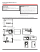
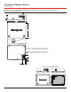
Figure 1. HPM Series Operation (standard version shown top down)
Signal
to MCU
Particle
Fan
Lens
Laser
source
Laser
drive
circuit
Air inlet
Light
trap
Connector
Photodiode
Photoelectric
converter
Air outlet
1
2
3
4
Fan draws in air through inlet.
Air passes through the laser where the light reflected off the
particles is captured by the photodiode.
The photodiode passes information to the photoelectric converter
The photoelectric converter processes the signal from the particles into density
.
Signal is transmitted to micro control unit where a proprietary
algorithm processes the data and supplies outputs for the density of the
particulate (
g/m
3
).
3
4
1
2
Table 3. Standard and Compact Connector Pinout
Standard Compact
Pin Name Description Pin Name Description
1 V
OUT
power output (+3.3 V/100 mA) 1 V
OUT
power output (+5 V)
(output max.: 300 mA)
2 V
CC
power input (5 V) 2 V
CC
power input (+5 V)
3 N/A N/A 3 GND ground
4 N/A N/A 4 GND ground
5 RES reserved for future use 5 RES reserved for future use
6 TX UART TX output (0 V - 3.3 V) 6 N/A N/A
7 RX UART RX input (0 V - 3.3 V) 7 RX UART RX input (0 V - 3.3 V)
8 GND ground 8 N/A N/A
-
— —
9 TX UART TX output (0 V - 3.3 V)
-
— —
10 SET reserved for future use
9
7
5
3
1
10
8
6
4
2
8 7 6 5 4 3 2 1