
Submittal Sheet
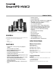

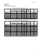
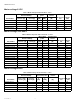
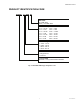

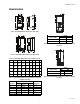
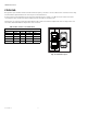


Table Of Contents
- general
- FEATURES
- specifications
- Models
- Product Identification Code
- Mechanical Mounting
- Dimensions
- cooling
- CABLING AND FUSES
- FEATURES / Functions
- Optional Accessories
- Informations d'ordre général
- CARACTÉRISTIQUES
- SPÉCIFICATIONS
- MODÈLES
- CODE D'IDENTIFICATION DES PRODUITS
- MONTAGE MÉCANIQUE
- DIMENSIONS
- REFROIDISSEMENT
- CÂBLAGE ET FUSIBLES
- CARACTÉRISTIQUES/FONCTIONS
- ACCESSOIRES EN OPTION

SMARTVFD HVAC2
31-00109EF—01 6
MECHANICAL MOUNTING
There are two possible ways to mount SmartVFD HVAC2 in
the wall. For MI1-MI3, either screw or DIN-rail mounting;
For MI4-MI5, screw or flange mounting.
Fig. 2. Screw mounting, MI1 - MI3
Fig. 3. Screw mounting, MI4 - MI5
NOTE: See the mounting dimensions on the back of the
drive.
Fig. 4. DIN-rail mounting, MI1 - MI3
Fig. 5. Flange mounting, MI4 - MI5
Fig. 6. Flange mounting cutout dimensions for MI4
[Unit: inches (mm)]
Fig. 7. Flange mounting cutout dimensions for MI5
[Unit: inches (mm)]
Fig. 8. Flange mounting depth dimensions for MI4 and
MI5 [Unit: inches (mm)]
=
M5
MI3
MI1
=M4
MI2
=M5
LOC
REM
BACK
RESET
OK
M36500
LOC
REM
BACK
RESET
OK
LOC
REM
BACK
RESET
OK
MI4
MI5
LOC
REM
BACK
RESET
OK
M36501
=M 6
=M 6
LOC
REM
BACK
RESET
OK
12
M36502
M36503
LOC
REM
BACK
RESET
OK
13/64 (6)
M36504
TOP
6
(153)
Ø 1/4 (7)
14-1/2 (370)
DRIVE OUTLINE
OPENING OUTLINE
14-19/64 (362)
14 (356)
15-7/64 (384)
6-1/2
(166)
6-51/64
(173)
7-13/32
(189)
OPENING OUTLINE
16 (407)
DRIVE OUTLINE
Ø 1/4 (7)
TOP
6
(153)
14 (356)
15-45/64 (400)
17 (431)
13/64 (6)
6-1/2
(166)
6-51/64
(173)
7-13/32
(189)
M36505
MI4
M36507
MI5
1-3/32
(29)
51/64
(20)
13
(332)
15/32
(12)
29/32
(23)
3-1/2
(89)
6-1/2 (165)
3
(77)
5/8
(16)
1-3/32
(29)
15
(379)
19/32
(15)
29/32
(23)
8 (202)
3-45/64
(95)
4-7/32
(107)