Ho Honeywell User Manual SmartVFD Compact Variable Frequency Drives for Constant and Variable Torque Applications 62-0312-03
Honeywell 1 User’s Manual Index 1. SAFETY .........................................................................................4 1.1 Warnings ...............................................................................4 1.2 Safety instructions .................................................................6 1.3 Grounding and Ground fault protection .................................6 1.4 Before running the motor .......................................................7 2. RECEIPT OF DELIVERY ......
2 Honeywell 7.2 Control I/O .............................................................................32 8. CONTROL PANEL .........................................................................34 8.1 General ..................................................................................34 8.2 Display ...................................................................................34 8.3 Keypad ..................................................................................35 8.
Honeywell 3 10.11 Easy usage menu (Control panel: Menu PAR -> P9) ........71 10.12 Fieldbus parameters (Control panel: Menu PAR -> S2) ....73 10.12.1 Modbus process data ..............................................
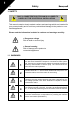
1 4 Safety Honeywell 1. SAFETY ONLY A COMPETENT ELECTRICIAN IS ALLOWED TO CARRY OUT THE ELECTRICAL INSTALLATION! This manual contains clearly marked cautions and warnings which are intended for your personal safety and to avoid any unintentional damage to the product or connected appliances. Please read the information included in cautions and warnings carefully: = Dangerous voltage Risk of death or severe injury = General warning Risk of damage to the product or connected appliances 1.
Safety Honeywell 6 7 5 If SmartVFD Compact is disconnected from mains while running the motor, it remains live if the motor is energized by the process. In this case the motor functions as a generator feeding energy to the frequency converter. After disconnecting the frequency converter from the mains, wait until the fan stops and the indicators on the display go out. Wait 5 more minutes before doing any work on SmartVFD Compact connections.
1 6 Safety Honeywell 1.2 SAFETY INSTRUCTIONS 1 The SmartVFD Compact frequency converter has been designed for fixed installations only. 2 Do not perform any measurements when the frequency converter is connected to the mains. 3 Do not perform any voltage withstand tests on any part of SmartVFD Compact. The product safety is fully tested at factory. 4 Prior to measurements on the motor or the motor cable, disconnect the motor cable from the frequency converter.
Honeywell Safety 1.4 BEFORE RUNNING THE MOTOR Checklist: Before starting the motor, check that the motor is mounted properly and ensure that the machine connected to the motor allows the motor to be started. Set the maximum motor speed (frequency) according to the motor and the machine connected to it. Before reversing the motor shaft rotation direction make sure that this can be done safely. Make sure that no power correction capacitors are connected to the motor cable.
8 Receipt of Delivery Honeywell 2. RECEIPT OF DELIVERY After unpacking the product, check that no signs of transport damages are to be found on the product and that the delivery is complete (compare the type designation of the product to the code below). Should the drive have been damaged during the shipping, please contact primarily the cargo insurance company or the carrier. If the delivery does not correspond to your order, contact the supplier immediately. 2.1 TYPE DESIGNATION CODE Figure 2.
Honeywell Receipt of Delivery 9 2.2 STORAGE If the frequency converter is to be kept in store before use make sure that the ambient conditions are acceptable: Storing temperature -40 °F(-40 °C)…+70 °F(21 °C) Relative humidity < 95%, no condensation 2.3 MAINTENANCE In normal operating conditions, SmartVFD Compact frequency converters are maintenance-free. 2.4 WARRANTY Only manufacturing defects are covered by the warranty.
3 10 Technical Data Honeywell 3. TECHNICAL DATA 3.1 SMARTVFD COMPACT TECHNICAL DATA Frame Dimensions and weight 0 - Uin Continuous rated current IN at ambient temperature max. 122 ºF (+50 ºC), overload 1.5 x IN max.
Technical Data Honeywell 11 3.2 POWER RATINGS 3.2.1 SmartVFD Compact - Mains voltage 208 - 240 V Mains voltage 208-240 V, 50/60 Hz, 1~ series Product code HVFDCD1B0003xxx HVFDCD1B0005xxx HVFDCD1B0007xxx HVFDCD1B0010xxx HVFDCD1B0015xxx HVFDCD1B0020xxx HVFDCD1B0030xxx Rated loadability 100% contin. current IN [ A ] 150% overload current [ A ] Motor shaft power P [ HP ] 1.7 2.4 2.8 3.7 4.8 7.0 9.6 2.6 3.6 4.2 5.6 7.2 10.5 14.4 0.25 0.5 0.75 1 1.
3 12 Technical Data Honeywell 3.2.3 SmartVFD Compact - Mains voltage 230 V, 3~ Mains voltage 208-240 V, 50/60 Hz, 3~ series Product code HVFDCD3B0003xxx HVFDCD3B0005xxx HVFDCD3B0007xxx HVFDCD3B0010xxx HVFDCD3B0015xxx HVFDCD3B0020xxx HVFDCD3B0030xxx Rated loadability Motor shaft power 100% contin. current IN [ A ] 150% overload current [ A ] P[ HP ] 1.7 2.4 2.8 3.7 4.8 7.0 11 2.6 3.6 4.2 5.6 7.2 10.5 16.5 0.33 0.5 0.75 1 1.5 2 3 Nomina Mechanical l input size and current weight (lb) [A] 2.7 3.
Technical Data Honeywell 13 3.2.5 SmartVFD Compact - Mains voltage 575 V, 3~ Mains voltage 575 V, 50/60 Hz, 3~ series Product code Rated loadability 100% contin. current IN [ A ] HVFDCD3D0010xxx HVFDCD3D0020xxx HVFDCD3D0030xxx HVFDCD3D0055xxx HVFDCD3D0075xxx HVFDCD3D0100xxx 1.7 2.7 3.9 6.1 9 11 150% overload current [A] 2.6 4.1 5.9 9.2 13.5 16.5 Motor shaft power P[ HP ] 1 2 3 5.4 7.5 10 Nomina Mechanical l input size and current weight (lb) [A] 2 3.6 5 7.6 10.4 14.1 MI3 2.18 MI3 2.18 MI3 2.
14 Installation Honeywell 4. INSTALLATION 4.1 MECHANICAL INSTALLATION There are two possible ways to mount the SmartVFD Compact to the wall - either screw or DIN-rail mounting. The mounting dimensions are given on the back of the drive and on the following page. MI1 MI2-3 =M 5 =M 4 Figure 4.1: Screw mounting 1 Figure 4.
Installation Honeywell 15 4.1.1 SmartVFD Compact dimensions W2 D2 W3 H1 H2 H3 Honeywell D1 W1 Figure 4.3: SmartVFD Compact dimensions, MI1-MI3 Type H1 H2 MI1 MI2 MI3 6. 7.7 10. 5.8 .4 .6 .5 .2 .9 0.3 6.7 3.5 0.2 4 0.3 7.2 2.5 9. 9. .9 .0 .2 .3 .3 H3 W1 W2 W3 D1 D2 Table 4.
16 Installation Honeywell 4.1.2 Cooling Forced air flow cooling is used in all SmartVFD Compact drives. Enough free space must be left above and below the frequency converter to ensure sufficient air circulation and cooling. The required dimensions for free space are given in the table below: Type MI1 MI2 MI3 Dimensions (inch) A 3.9 3.9 3.9 A B 2.0 2.0 2.0 Table 4.2 : Dimensions required for cooling Type Cooling air required (CFM) MI1 MI2 MI3 5.89 5.89 17.7 Honeywell B Table 4.
Honeywell Installation 17 Category C4: The drives of this class do not provide EMC emission protection. These kinds of drives are mounted in enclosures. NOTE: An external EMC filter is usually required to fulfil the EMC emission requirements. Category C4 for IT networks: Frequency converters of this class fulfil the product standard EN 61800-3 (2004) if intended to be used in IT systems.
18 Installation Honeywell 4.2 CABLING AND CONNECTIONS 4.2.1 Power cabling Note! Tightening torque for power cables is 4 - 5 in-lbs. 3~ (400V) Motor out 1~ (230V) Strip the plastic cable coating for 360° grounding MOTOR MAINS Figure 4.4: SmartVFD Compact power connections, MI1 3~ (400V) 1~ (230V) External brake resistor (400V) Motor out L1 L2/N L3 R+ R- U/T1 V/T2 W/T3 Strip the plastic cable coating for 360° grounding MAINS BRAKE RESISTOR MOTOR Figure 4.
Installation Honeywell 19 4.2.2 Control cabling Attach the support AFTER installing the power cables Honeywell Attach this plate BEFORE installing the power cables Figure 4.
20 Installation Honeywell Figure 4.7: Open the cover Control cable tightening torque: 3 in-lbs Strip the plastic cable coating for 360°earthing Figure 4.8: Install the control cables. See Chapter 7.
Installation Honeywell 21 4.2.3 Cable and fuse specifications Use cables with heat resistance of at least 158 °F (+70 °C). The cables and the fuses must be sized according to the tables below. Installation of cables according to UL regulations is presented in Chapter 4.2.6. The fuses also function as cable overload protection. These instructions apply only to cases with one motor and one cable connection from the frequency converter to the motor. In any other case, ask the factory for more information.
22 Installation Frame Type IN [A] Fuse [A] MI1 MI2 MI3 P37 - 1P1 1P5 - 2P2 3P0 - 5P5 1,9-3,3 4,3-5,6 7,6 - 12 6 10 20 Honeywell Terminal cable size (min/max) Mains Main Ground Control Relay cable Cu [AWG] terminal terminal terminal terminal 3*15+15 3*15+15 3*13+13 [AWG] [AWG] [AWG] [AWG] 15-11 15-11 15-9 15-11 15-11 15-9 20-15 20-15 20-15 20-15 20-15 20-15 Table 4.
Installation Honeywell 23 4.2.5 Stripping lengths of motor and mains cables Ground conductor 0.3 in 0.3 in 1.4 in 0.8 in Figure 4.9: Stripping of cables Note! Strip also the plastic cover of the cables for 360 degree grounding. See Figures 4.4, 4.5 and 4.8. 4.2.6 Cable installation and the UL standards To meet the UL (Underwriters Laboratories) regulations, a UL-approved copper cable with a minimum heat-resistance of 140/167 °F (+60/75 °C) must be used. 4.2.
24 Installation Honeywell 3. Motor insulation checks Disconnect the motor cable from the motor and open the bridging connections in the motor connection box. Measure the insulation resistance of each motor winding. The measurement voltage must equal at least the motor nominal voltage but not exceed 1000 V. The insulation resistance must be >1MOhm.
Commissioning Honeywell 25 5. COMMISSIONING Before commissioning, note the warnings and instructions listed in Chapter 1! 5.1 COMMISSIONING STEPS OF SMARTVFD COMPACT 1 2 Read carefully the safety instructions in Chapter 1 and follow them. After the installation, make sure that: • both the frequency converter and the motor are grounded • the mains and motor cables comply with the requirements given in Chapter 4.2.
5 26 Commissioning Honeywell Perform test run without motor. Perform either Test A or Test B: 7 A) Control from the I/O terminals: • Turn the Start/Stop switch to ON position. • Change the frequency reference (potentiometer) • Check in the Monitoring Menu that the value of Output frequency changes according to the change of frequency reference. • Turn the Start/Stop switch to OFF position B) Control from the keypad: • Select the keypad as the control place with par. 2.1.
Honeywell Fault Tracing 27 6. FAULT TRACING Note: The fault codes listed in this chapter are visible if the Application Interface has a display, like e.g. in API FULL or API LIMITED or if a personal computer has been connected to the drive When a fault is detected by the frequency converter control electronics, the drive is stopped and the symbol F together with the ordinal number of the fault and the fault code appear on the display in the following format, e.
28 Fault Tracing Fault code Fault name 8 System fault • component failure • faulty operation Correcting actions Reset the fault and restart. Should the fault re-occur, contact the distributor near to you The DC-link voltage has exceeded the internal safety limit: • most probable cause: too low a supply voltage • frequency converter internal fault • Power outages In case of temporary supply voltage break reset the fault and restart the frequency converter. Check the supply voltage.
Honeywell Fault code Fault name Fault Tracing Possible cause 35 Application fault Application does not function 50 Analogue input Iin < 4mA (selected signal range 4 to 20 mA) Current at the analogue input is < 4mA • control cable is broken or loose • signal source has failed 51 External fault 53 Fieldbus fault Digital input fault. Digital input has been programmed as external fault input and this input is active.
7 30 API Honeywell 7. SMARTVFD COMPACT APPLICATION INTERFACE 7.1 INTRODUCTION There are three versions of Application Interfaces (API) available for the SmartVFD Compact drive: API Full API Limited API RS-485 (Modbus RTU) 6 Digital inputs 3 Digital inputs 1 Digital input 2 Analogue inputs 1 Analogue input 1 Relay output 1 Analogue output 1 Relay output RS-485 Interface 1 Digital output RS-485 Interface 2 Relay outputs RS-485 Interface Table 7.
Honeywell API • Current signal input fault • External fault • Undervoltage fault • Ground fault • Motor thermal, stall and underload protection • Fieldbus communication Special features in API Full and API Limited: • 8 preset speeds • Analogue input range selection, signal scaling and filtering • PI-controller 31 7
7 32 API 7.2 CONTROL I/O Honeywell API FULL Signal Terminal 1 +10Vre Ref. voltage out Analog signal in 1 2 AI1 Factory preset Freq. reference P) Description Maximum load 10 mA 0 - +10 V Ri = 200 k Ω (min) 3 6 GND 24Vout I/O signal ground 24V output for DI's ± 20 %, max.
API Honeywell 33 API LIMITED Signal Terminal 1 +10Vre Ref. voltage out Analog signal in 1 2 AI1 3 6 GND 24Vout Factory preset Freq. reference P) I/O signal ground 24V output for DI's Description Maximum load 10 mA 0 - +10 V Ri = 200 k Ω ± 20 %, max.
34 Control Panel Honeywell 8. CONTROL PANEL 8.1 GENERAL The SmartVFD Compact API Full and API Limited versions have similar control panels. The panel is integrated to the drive consisting of corresponding application card and an overlay on the drive cover with status display and button clarifications. The Control panel consists of an LCD display with backlight and a keypad including a navigation wheel, a green START button and a red STOP button (see Figure 8.1). 8.
Honeywell Control Panel 35 Figure 8.1: SmartVFD Compact Control panel 8.3 KEYPAD The keypad section of the control panel consists of a navigation wheel and START and STOP buttons (see Figure 8.1). The navigation wheel is used for navigating on the panel display, but it also works as a reference potentiometer when KEYPAD has been selected as the control place of the drive. The wheel has two separate functions; - rotating the wheel e.g.
36 Control Panel Honeywell 8.4 NAVIGATION ON THE SMARTVFD COMPACT CONTROL PANEL This chapter provides you with information on navigating the menus on SmartVFD Compact and editing the values of the parameters. 8.4.1 Main menu The menu structure of SmartVFD Compact control software consists of a main menu and several submenus. Navigation in the main menu is shown below: REFERENCE REF MENU Displays the MON keypad reference value PAR regardless of FLT the selected control place.
Control Panel Honeywell 37 8.4.2 Reference menu READY RUN STOP ALARM FAULT REF MON PAR Hz FLT FWD REV Push to enter edit mode I/O KEYPAD Change value BUS Push to confirm Figure 8.3: Reference menu display Move to the reference menu with the navigation wheel (see Figure 8.2). The reference value can be changed with the navigation wheel as shown in Figure 8.3. The reference value follows the rotation continuously (= without separate new value acceptance) .
38 Control Panel Honeywell 8.4.3 Monitoring menu Alternates in the display READY RUN STOP ALARM FAULT REF MON PAR Hz FLT FWD REV I/O KEYPAD BUS Browse M1.1 - M1.20 Figure 8.4: Monitoring menu display Monitoring values mean actual values of measured signals as well as statuses of some control settings. They are visible in API Full and Limited display, but they cannot be edited. The monitoring values are listed in Table 8.1.
Honeywell Code Monitoring signal M1.7 Motor voltage Control Panel Unit ID Description V 6 Motor voltage M1.8 DC-link voltage V 7 Measured DC-link voltage M1.9 Unit temperature C ° 8 Heat sink temperature M1.10 Motor temperature C ° M1.11 Analogue input 1 % 13 AI1 value M1.12 Analogue input 2 % 14 AI2 value ONLY IN API FULL! M1.13 Analogue output % 26 AO1 ONLY IN API FULL! M1.14 DI1, DI2, DI3 15 Digital input statuses M1.
40 Control Panel Honeywell 8.4.4 Parameter menu In Parameter menu only the Quick setup parameter list is shown by default. By giving the right value to the parameter 13.1 it is possible to open other advanced parameter groups. The parameter lists and descriptions can be found in chapters 9 and 10. The following figure shows the parameter menu view: Alternates in the display READY RUN STOP ALARM FAULT REF MON PAR Hz FLT FWD Browse P1.1 -> REV I/O Push to enter edit mode Figure 8.
Control Panel Honeywell 41 8.4.5 Fault history menu READY RUN STOP ALARM FAULT READY RUN STOP ALARM FAULT REF REF ON MON AR PAR FLT FLT FWD REV I/O KEYPAD BUS Push FWD REV I/O KEYPAD BUS Browse faults 1-9 READY RUN STOP ALARM FAULT READY RUN STOP ALARM FAULT REF REF MON MON PAR PAR FLT FWD REV I/O KEYPAD BUS Push FLT FWD REV I/O KEYPAD BUS Browse for hours (H), minutes (M) and seconds (S) Figure 8.
42 Control Panel Note! The whole fault history can be cleared by pressing STOP button for 5 sec time when the drive is stopped and Fault history menu is selected in the display.
Honeywell Parameters 43 9. GENERAL PURPOSE APPLICATION PARAMETERS On the next pages you can find the lists of parameters within the respective parameter groups. The parameter descriptions are given in Chapter 10.
9 44 Parameters Honeywell 9.1 QUICK SETUP PARAMETERS (VIRTUAL MENU, SHOWS WHEN PAR. 13.1 = 1) Code Parameter Min Max Unit Default ID Note P1.1 Motor nominal voltage 180 500 V 230 400 110 Check rating plate on the motor P1.2 Motor nom. frequency 30 320 Hz 60.00 111 Check rating plate on the motor P1.3 Motor nominal speed 300 2000 0 rpm 1440 112 Default applies for a 4pole motor. P1.4 Motor nominal current 0.2 x INunit 1.
Parameters Honeywell 45 Code Parameter Min Max Unit Default ID Note P4.3 Deceleration time 0.1 3000 s 1.0 104 Deceleration time from maximum frequency to 0 Hz. P6.1 AI1 Signal range 0 3 0 379 API FULL and LIMITED: 0 = Voltage 0…10 V 1 = Voltage 2…10 V API LIMITED ONLY: 2 = Current 0…20 mA 3 = Current 4…20 mA NOTE: When using API LIMITED, select the voltage/current range also with the dip switch P6.
9 46 Parameters Honeywell 9.2 MOTOR SETTINGS (CONTROL PANEL: MENU PAR -> P1) Code Parameter Min Max Unit Default ID Note P1.1 Motor nominal volt180 age 500 V 230 400 110 Check rating plate on the motor P1.2 Motor nominal frequency 30 320 Hz 50.00 111 Check rating plate on the motor P1.3 Motor nominal speed 300 2000 0 rpm 1440 112 Default applies for a 4pole motor. P1.4 Motor nominal current 0.2 x INunit 1.5 x INunit A INunit 113 Check rating plate on the motor P1.
Parameters Honeywell 47 9.3 START/STOP SETUP (CONTROL PANEL: MENU PAR -> P2) Code Parameter Min Max Default ID P2.1 Control place 1 3 1 1 = I/O terminal 125 2 = Keypad 3 = Fieldbus P2.2 Start function 0 1 0 505 0 = Ramp 1 = Flying start P2.3 Stop function 0 1 0 506 0 = Coasting 1 = Ramp P2.4 Start/Stop logic 0 DI1 DI2 0 Start Fwd Start reverse 1 Start Reverse 300 2 Start Pulse Stop Pulse 3 Start Fwd Start Rv REAF REAF 0 Unit 3 Note Table 9.3: Start/stop setup 9.
9 48 Parameters Honeywell 9.5 RAMPS AND BRAKES SETUP (CONTROL PANEL: MENU PAR -> P4) Code P4.1 Parameter Min Max Default s 0.0 ID Note 500 0 = Linear >0 = S-curve ramp time 0.0 P4.2 Acceleration time 0.1 3000 s 1.0 103 P4.3 Deceleration time 0.1 3000 s 1.0 104 P4.4 DC braking current Unit dep. Unit dep. A Varies 507 P4.5 DC braking time at start 0.00 600.00 s 0 516 P4.6 Frequency to start DC braking during 0.10 ramp stop 10.00 1.50 515 P4.
Parameters Honeywell Code Parameter Min Max Default ID Note P5.10 Preset speed B2 0 6 0 421 As parameter 5.1 P5.11 Disable PI 0 6 6 102 0 As parameter 5.1 Table 9.
9 50 Parameters Honeywell 9.7 ANALOGUE INPUTS (CONTROL PANEL: MENU PAR -> P6) Code Parameter Min Max Unit Default ID Note Only in API FULL & LIMITED P6.1 0 API FULL and LIMITED: 0 = Voltage 0…10 V 1 = Voltage 2…10 V API LIMITED ONLY: 379 2 = Current 0…20 mA 3 = Current 4…20 mA NOTE: When using API LIMITED, select the voltage/current range also with the dip switch AI1 Signal range 0 3 P6.2 AI1 filter time 0.0 10.0 0.1 378 0 = no filtering P6.3 AI1 Custom min -100.0 100.0 % 0.
Parameters Honeywell Code Parameter Min Max P7.2 Relay output 2 content 0 8 P7.3 Digital output 1 content 0 8 Unit 51 Default ID 3 314 As parameter 7.1 Selections Only in API FULL 1 312 As parameter 7.1 P7.4 Analogue output function 0 4 1 0 = Not in use 1 = Output freq. (0-fmax) 2 = Output current (0307 InMotor) 3 = Torque (0-Nominal torque) 4 = PI controller output P7.5 Analogue output minimum 0 1 1 310 Table 9.
9 52 Parameters Honeywell 9.9 PROTECTIONS (CONTROL PANEL: MENU PAR -> P9) Code Parameter Default ID P9.1 Response to 4mA 0 reference fault Min 2 Max Unit 1 700 P9.2 Response to under voltage fault 0 2 2 727 P9.3 Ground fault protection 0 2 2 P9.4 Stall protection 0 2 0 0 = No response 703 1 = Warning 2 = Fault, stop acc. to 709 P2.3 P9.5 Underload protec0 tion 2 0 713 P9.6 Reserved 0 704 P9.7 Thermal protection of the motor P9.8 Motor ambient temperature P9.
Parameters Honeywell 53 9.10 AUTORESTART PARAMETERS (CONTROL PANEL: MENU PAR -> P10 ) Code Parameter P10.1 Wait time Min Max Unit 0.10 10.00 s Default ID Note 0.50 Delay before automatic 717 restart after a fault has disappeared P10.2 Trial time 0.00 60.00 s 30.00 Defines the time before the frequency converter tries to 718 automatically restart the motor after the fault has disappeared P10.3 Start function 0 2 0 0 = Ramp 719 1 = Flying start 2 = According to P4.2 P10.
9 54 Parameters Honeywell 9.11 PI CONTROL PARAMETERS (CONTROL PANEL: MENU PAR -> P12) Code Parameter Min P12.1 PI activation 0 P12.2 PI controller gain Max Unit 2 Default 0 0.0 1000 100.0 118 P12.3 PI controller Itime 0.00 320.0 s 10.00 119 P12.4 Keypad PI reference 0.0 100.0 % 0.0 167 P12.5 Setpoint source 0 % ID 163 3 0 332 Note 0 = Not used 1 = PI for motor control 2 = PI for external use 0 = Keypad PI reference, P12.
Parameters Honeywell 55 9.12 EASY USAGE MENU (CONTROL PANEL: MENU PAR -> P0) Code Parameter Min Max Parameter P13.1 conceal 0 1 P13.2 Drive setup 0 Unit 3 Default ID Note 1 0 = All parameters visible 115 1 = Only quick setup parameter group visible 0 0 = Basic 1 = Pump drive 2 = Fan drive 540 3 = Conveyor drive (HP) NOTE! Visible only duriing Startup wizard Table 9.12: Easy usage menu parameters 9.
9 56 Parameters Code Parameter S2.8 Reset communication status Min Max Default Honeywell Note 1= Resets par. S2.1 Total counters (MENU PAR -> S3) S3.1 MWh counter S3.2 Power on days S3.3 Power on hours User settings (MENU PAR -> S4) S4.1 Display contrast 0 15 7 Adjusts the display contrast S4.2 Restore factory defaults 0 1 0 1= Restores factory defaults for all parameters Table 9.13: System parameters NOTE! These parameters are shown, when P13.1 = 0.
Honeywell Parameter Descriptions 57 10. PARAMETER DESCRIPTIONS On the next pages you can find the descriptions of certain parameters. The descriptions have been arranged according to parameter group and number. 10.1 MOTOR SETTINGS (CONTROL PANEL: MENU PAR -> P1) 1.8 MOTOR CONTROL MODE With this parameter the user can select the motor control mode.
58 Parameter Descriptions Honeywell U[V] Un par.1.11 Default: Nominal Field weakening point voltage of the motor Linear Squared Default: Nominal frequency of the motor par. 1.14 f[Hz] par.1.10 Figure 10.1: Linear and squared change of motor voltage 2 = Programmable U/f curve: The U/f curve can be programmed with three different points. Programmable U/f curve can be used if the other settings do not satisfy the needs of the application U[V] Un Par 1.
Honeywell Parameter Descriptions 59 1.10 FIELD WEAKENING POINT The field weakening point is the output frequency at which the output voltage reaches the value set with par. 1.11. 1.11 VOLTAGE AT FIELD WEAKENING POINT Above the frequency at the field weakening point, the output voltage remains at the value set with this parameter. Below the frequency at the field weakening point, the output voltage depends on the setting of the U/f curve parameters. See parameters 1.9 - 1.14 and Figures 10.1 and 10.2.
60 Parameter Descriptions Honeywell Switching frequency for SmartVFD Compact: 1.5…16 kHz. 1.17 BRAKE CHOPPER Note! An internal brake chopper is installed in three phase supply MI2 and MI3 size drives 0 = No brake chopper used 1 = Brake chopper used in Run state 2 = Used in Run and Stop state When the frequency converter is decelerating the motor, the energy stored to the inertia of the motor and the load are fed into an external brake resistor, if the brake chopper has been activated.
Honeywell Parameter Descriptions 61 1 = Flying start The frequency converter is able to start also a running motor by applying a small torque to motor and searching for the frequency corresponding to the speed the motor is running at. The searching starts from the maximum frequency towards the actual frequency until the correct value is detected. Thereafter, the output frequency will be increased/decreased to the set reference value according to the set acceleration/deceleration parameters.
62 Parameter Descriptions Honeywell 10.3 FREQUENCY REFERENCES (CONTROL PANEL: MENU PAR -> P3) 3.3 I/O REFERENCE Defines the selected frequency reference source when the drive is controlled from the I/O terminal. 0 = Preset speed 0 - 7 1 = Keypad reference 2 = Reference from Fieldbus (FBSpeedReference) 3 = AI1 reference (terminals 2 and 3, e.g. potentiometer) 4 = AI2 reference (terminal 4 and 5, e.g. transducer) 3.4 - 3.
Parameter Descriptions Honeywell 63 Setting value 0.1…10 seconds for this parameter produces an S-shaped acceleration/deceleration. The acceleration and deceleration times are determined with parameters 4.2 and 4.3. [Hz] P4.2, 4.3 P4.1 P4.1 [t] Figure 10.3: S-shaped acceleration/deceleration 4.5 DC BRAKING TIME AT START DC-brake is activated when the start command is given. This parameter defines the time before the brake is released.
64 Parameter Descriptions 4.7 Honeywell DC BRAKING TIME AT STOP Determines if braking is ON or OFF and the braking time of the DC-brake when the motor is stopping. The function of the DC-brake depends on the stop function, par. 2.3. 0 = DC brake is not in use >0 = DC brake is in use and its function depends on the Stop function, (par. 2.3). The DC braking time is determined with this parameter. Par. 2.
Parameter Descriptions Honeywell 65 The braking time is defined with parameter 4.7. If high inertia exists, it is recommended to use an external braking resistor for faster deceleration. See Figure 10.6. fout Motor speed Output frequency DC-braking Par. 4.6 t t = par. 4.7 RUN STOP Figure 10.6: DC-braking time when Stop mode = Ramp 10.5 DIGITAL INPUTS (CONTROL PANEL: MENU PAR -> P5) 5.1 5.2 5.3 5.4 5.5 5.6 5.7 5.8 5.9 5.10 5.
66 Parameter Descriptions Honeywell 10.6 ANALOQUE INPUTS (CONTROL PANEL: MENU PAR -> P6) 6.2 6.6 AI1 SIGNAL FILTER TIME (ONLY IN API FULL & LIMITED) AI2 SIGNAL FILTER TIME (ONLY IN API FULL) This parameter, given a value greater than 0, activates the function that filters out disturbances from the incoming analogue signal. Long filtering time makes the regulation response slower. See Figure 10.7. % Unfiltered signal 100% Filtered signal 63% t [s] Par. 6.2 Par. 6.6 Figure 10.
Parameter Descriptions Honeywell 67 10.7 DIGITAL AND ANALOQUE OUTPUTS (CONTROL PANEL: MENU PAR -> P7) 7.1 7.2 7.
68 Parameter Descriptions Honeywell 9.7 THERMAL PROTECTION OF THE MOTOR 0 = No response 1 = Warning 2 = Fault, stop mode after fault according to parameter 2.3 If tripping is selected the drive will stop and activate the fault stage. Deactivating the protection, i.e. setting parameter to 0, will reset the thermal model of the motor to 0%. 9.8 MOTOR AMBIENT TEMPERATURE When the motor ambient temperature must be taken into consideration, it is recommended to set a value for this parameter.
Parameter Descriptions Honeywell 69 If the motor's t6-time (t6 is the time in seconds the motor can safely operate at six times the rated current) is known (given by the motor manufacturer) the time constant parameter can be set basing on it. As a rule of thumb, the motor thermal time constant in minutes equals to 2xt6. If the drive is in stop state the time constant is internally increased to three times the set parameter value. See also Figure 10.9.
70 Parameter Descriptions Wait t ime par.10.1 Wait time par.10.1 Honeywell Wait time par.10.1 Fault trigger Motor stop signal Restart 1 Restart 2 Motor start signal Supervision Trial time par.10.2 Fault active RESET/ Fault reset Autoreset function: (Trials = 2) Figure 10.10: Automatic restart 10.10 PI CONTROL PARAMETERS (CONTROL PANEL: MENU PAR -> P12) 12.2 PI CONTROLLER GAIN This parameter defines the gain of the PI controller.
Parameter Descriptions Honeywell 71 Controller feedback (%) par. 12.8 par. 12.7 0V 0mA Custom min par. 6.3/6.7 Custom max par.6.4/6.8 10V 20mA Analoque input with custom min and max scaling (%) Figure 10.11: Feedback minimum and maximum 10.11 EASY USAGE MENU (CONTROL PANEL: MENU PAR -> P9) 13.2 DRIVE SETUP With this parameter you can easily set up your drive for four different applications. Note! This parameter is only visible when the Startup Wizard is active.
72 Parameter Descriptions Honeywell Alternates in the display READY RUN STOP A LARM FAULT READY RUN STOP ALARM FAULT REF REF MON MON PA R PAR FLT FLT 1 Press STOP for 5 seconds in main menu 4 PERFORM THE SAME PROCEDURE FOR PAR. 1.4, MOTOR NOMINAL CURRENT PAR rp m 2 Push to enter edit mode 5 FLT 3 Select motor nominal speed and push to confirm. PERFORM DRIVE SETUP, PAR. 13.2, SEE NEXT PAGE Figure 10.
Parameter Descriptions Honeywell READY RUN STOP A LARM FAULT READY RUN STOP ALARM FAULT READY R UN STOP ALARM FAULT REF REF REF MON MON MON PA R PAR PAR FLT FLT FLT 1 Startup wizard shows par 13.2 number. 2 Push to enter edit mode. 73 3 Select between 0 - 3, see below! Selections: P1.1 P1.2 P1.7 P1.15 P2.1 P2.2 P2.3 P3.1 P3.2 P3.3 P4.2 P4.
74 Parameter Descriptions Honeywell - 04 Read Input Registers - 06 Preset Single Registers 10.12.1 Modbus process data Process data is an address area for fieldbus control. Fieldbus control is active when the value of parameter 2.1 (Control place) is 3 (=fieldbus). The contents of the process data has been determined in the application. The following tables present the process data contents in the GP Application. Table 10.
Parameter Descriptions Honeywell 75 Table 10.5: Status Word: 15 14 13 12 11 10 9 8 7 6 5 4 3 2 1 0 - - - - - - - - - Z AREF W FLT DIR RUN RDY Information about the status of the device and messages is indicated in the Status word. The Status word is composed of 16 bits the meanings of which are described in the table below: Table 10.6: Actual speed: 15 14 13 12 11 10 9 8 7 6 5 4 3 2 1 MSB 0 LSB This is actual speed of the frequency converter.
76 Parameter Descriptions Honeywell Table 10.
62-0269-02.fm Page 24 Tuesday, October 14, 2008 6:55 AM COMPACT VARIABLE FREQUENCY DRIVE (DPD00128A) Automation and Control Solutions Honeywell International Inc. Honeywell Limited-Honeywell Limitée 1985 Douglas Drive North 35 Dynamic Drive Golden Valley, MN 55422 Toronto, Ontario M1V 4Z9 customer.honeywell.com ® U.S. Registered Trademark © 2011 Honeywell International Inc. 62-0312—03 T.D. Rev.