
User Guide

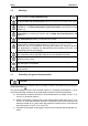
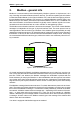
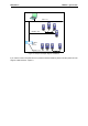

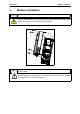
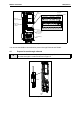
Table Of Contents
- 1. Safety
- 2. Modbus - general info
- 3. Modbus technical data
- 4. Modbus installation
- 5. Programming
- 5.2.1 Ethernet common settings (M5.8.1)
- 5.2.2 Modbus TCP settings (M5.8.2)
- 5.3.1 Modbus RTU Parameters
- 5.3.2 Modbus RTU monitoring values
- 5.4.1 Ethernet common settings
- 5.4.2 Modbus TCP settings
- 5.4.2.1 Common settings
- 5.4.3 Modbus TCP monitoring values
- 5.4.3.1 Connection 1
- 5.4.3.2 Connection 2
- 6.3.1 Coil registers
- 6.3.2 Input discrete registers
- 6.3.3 Holding and input registers
- 6.3.3.1 Drive Application ID’s
- 6.3.3.2 FB Process data IN
- 6.3.3.3 FB Process data OUT
- 6.3.3.4 ID map
- 6.3.3.5 Operation day counter
- 6.3.3.6 Resettable operation day counter
- 6.3.3.7 Energy counter
- 6.3.3.8 Resettable energy counter
- 6.3.3.9 Fault history

Honeywell • 8 Modbus installation
4. Modbus installation
Figure 3.
1
Open the cover of the AC drive.
The relay outputs and other I/O-terminals may have a dangerous control voltage
present even when drive is disconnected from mains.
2
Locate the components that you will need on the AC drive to connect and run the
Modbus cables.
Be sure not to plug the Modbus TCP cable to the terminal under the keypad!
This might harm your personal computer.
DANGER
WARNING