
Submittal Sheet
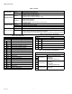

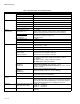
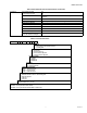
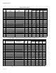
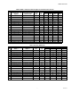

Table Of Contents

SMARTVFD HVAC
63-4520—08 2
Table 1. General.
Communication
RS485 Standard: Modbus™ RTU, BACnet, N2
Ethernet Standard: Modbus/TCP, BACnet/IP
Software features
Energy-saving
functions
• Real-time clock for timed functions
• Energy monitor for kWh monitoring
• Sleep function to minimize downtime energy
Protections
• Overload and underload protections (e.g. broken fan and dry pump)
• Motor thermal protection
• Missing phase detection
• Automatic reset to avoid interruption of the process
Process control
2 * PID For process control
Multipump For replacing the pump controller
Flying start For tripless catching of spinning fan
Human interfaces
Keypad Graphical display with built-in manual and wizards.
PC Tools • PC Commissioning Tool for easy commissioning, monitoring, and troubleshooting.
• Energy Savings calculator to estimate cost avoidance.
• Product selection tool for selecting VFD and bypass, and creating submittal documents.
Table 2. I/O Connections.
Basic I/O Board
Terminal Signal
1 +10 Reference output
2 AI1+ Analogue input, voltage or current
3 AI1- Analogue input common (current)
4 AI2+ Analogue input, voltage or current
5 AI2- Analogue input common (current)
6 24 24 V aux. voltage
7 GND I/O ground
8 DI1 Digital input 1
9 DI2 Digital input 2
10 DI3 Digital input 3
11 CM Common A for DI1-DI6
12 24 24 V aux. voltage
13 GND I/O ground
14 DI4 Digital input 4
15 DI5 Digital input 5
16 DI6 Digital input 6
17 CM Common A for DI1-DI6
18 AO1+ Analogue signal (+output)
19 AO-/
GND
Analogue output common
30 +24 24 V auxiliary input voltage
A RS485 Differential receiver/transmitter
B RS485 Differential receiver/transmitter
Table 3. I/O Connections, Relay Board 2.
Relay Board 2
Terminal Signal
21
Relay output 1*
Switching capacity24VDC/8A
250VAC/8A
125VDC/0.4A
Min.switching load5V/10mA
22
23
24
Relay output 2*
Switching capacity24VDC/8A
250VAC/8A
125VDC/0.4A
Min.switching load5V/10mA
25
26
28
Thermistor input
Rtrip = 4.7 kΩ (PTC); Measuring
voltage 3.5V
29
Table 2. I/O Connections. (Continued)
Basic I/O Board
Terminal Signal