
Application Guide


63-706219
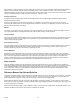
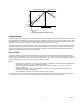
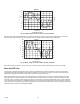
Motor Speed
Te
rm
ina
l
Vo
lta
ge
Design Max Motor Torque
Auto Boost
Fixed
Boost
De
sig
n
Ma
x
Sp
ee
d
Theoretical Terminal
Voltage
100%
100%
Motor Torque
Field Weakening Point
Fig. 20. VFD voltage to frequency ratio.
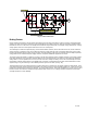
Charging Resistor
The charging resistor is included in the DC bus to provide current limiting during the initial power up stages of the VFD. When a
fully discharged VFD is switched on to the power supply, the capacitors on the DC bus are seen by the power supply as a very
low impedance load. If the design does not include a charging resistor, the current surge magnitude would be so high that the
input bridge can be damaged, or require up-rating far beyond that required for normal running.
The power supply capacity, cable lengths have a bearing on the magnitude of this surge current. With the charging resistor in
the circuit, the current surge is limited until the Vdc rises above about 380 volts. At this point, a contactor or solid state switch
shorts out the resistor. The charging circuit is short time rated, repeated power down/up cycles will ultimately cause failure.
Typically 10 power up/down cycles per hour are acceptable.
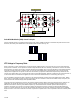
AC Line Choke
The AC Line choke design provides some smoothing on the DC bus and reduces the amount of ripple current that must be
tolerated by the main capacitors. This has an effect of extending the life of these components. The choke provides a limiting
function to the magnitude of the DC bus current during normal operation. This results in an improved overall power factor of the
VFD and reduced harmonic currents flowing in the power distribution network.
NOTES:
— Be aware that if multiple VFDs or one large VFD installed on a distribution network that supports equipment that
also produces harmonic currents, the effects are cumulative.
— If power factor correction equipment is also installed on the network, damage can occur to the correction
equipment capacitors.
— Limiting the amount of harmonic current flowing in the network can require additional power line reactors, or
under extreme conditions, a filter network.
— Only an Harmonic Survey can guarantee the quality of the power supply.
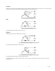
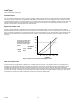
To illustrate this point, a test was carried out with a standard 4 pole three-phase motor connected first to no load and then full
load, driven by a VFD. Fig. 21 and 22 show the voltage and current waveforms under these two conditions.