
Application Guide


63-706225
Where the environment is dusty and in particular if the dust is of a conductive nature, then the cooling air should be filtered
prior to injection into the VFD enclosure. Again, if the environment is particularly dirty, the enclosure may be sized to provide
sufficient natural cooling or a refrigeration unit may be installed. Refer to the technical manual for the individual machine for
specific details on mounting and spacing between machines.
Under no circumstances must the VFD be installed within a hazardous area, an area where there is potential for presence of
an explosive mixture surrounding the VFD. It may be that the VFD can be installed outside the hazardous area driving a motor
within the hazardous area. In this particular circumstance, approvals and special testing are required.
Motor, Control Gear and Power Supply
Take the motor full name plate details, do not assume anything. If the name plate is missing then take full load current readings
and measure the supply voltage.
Where there is a local isolator or contactors on the output of the VFD, try to ensure that these devices are interfaced with the
VFD via
late make/early break
auxiliary contacts. This ensures that the VFD is aware that the switch is about to be opened
before the main contacts open. If programmed correctly, it ensures trouble-free operation. During the opening of a switch
controlling an inductive load, such as a motor, very high voltages can be created as the magnetic flux decays. Values as high
as 4000 volts have been measured on a standard 400 volt circuit. If these high voltages are allowed to reach the VFD,
unpredictable results may occur at the very least or possibly at worst, damage may occur to the power devices within the VFD.
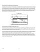
What type of load is the motor driving - if its a fan or a centrifugal pump, then normally there will be no problems, however with
process machines, the type of load characteristics can be very important e.g. grinding and mixing machines have very high
starting torque requirements (and therefore current demand) whilst once up to speed, the current demand may only be 50% of
motor nameplate current.
Beware of old motors. Many motors still in operation have not been rewound in 30 or 40 years of operation. The quality of the
insulation materials used in old motors is not often able to cope with the stresses imposed by a VFD. If an old motor is being
considered for speed control it would be wise to check if the machine has been rewound in that last 10-15 years. If it has not,
then there is potential for a motor failure within a very short period after the VFD is installed.
Effects of Speed Control
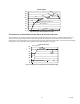
Be aware that the system being served by the motor, which is being considered for speed control, may not be able to accept a
varying volumes or special consideration may be required. Typical examples would be chilled water pumps feeding chillers and
heating water pumps feeding boilers. Centrifugal or screw-type chillers usually have temperature control on the leaving water
side of the machine. This will provide the feedback to the chiller so that it can reduce capacity without adverse effects. There is
however a minimum flow rate that the machine will accept before problems occur. Laminar flow through the tube bundle is a
typical example. Refer to manufacturers details carefully before considering this type of application - but it can be done
successfully.
On chillers with reciprocating compressors, the temperature controls often placed in the flow on to the machine. In this case the
temperature control system would not see the reduced flow and a trip on low leaving water temperature will occur. Special
consideration is required.
Boilers are another example where if the flow rate through the machine is reduced too much, problems can occur. The boiler
requires a minimum flow rate to produce turbulence within the heat exchanger in order to control
hot spots
. If the flow rate is
reduced below this value then there is a possibility of
hot spots
occurring resulting in damage to the heat exchanger
IMPORTANT
Ensure that the user is fully aware of and agrees with the implications of applying speed control before proceeding.
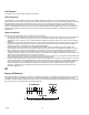
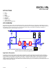
EMC Wiring and RFI Filters
— Mount the RFI Filter as close as possible to the VFD input terminals, with cables as short as possible. Install at least one
ferrite ring on the VFD output. Pass all conductors through the same ring. If possible, put one full turn of each conductor
around the ring. If this is not possible and there are problems, add additional ferrite rings.
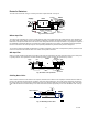
— Connect the filter to ground via its own earth strap, at least 1/2 in. (10 mm) wide and as short as possible.
— Use armored or shielded cable from the VFD to the motor. Connect the armor gland to the motor frame and the VFD main
earth terminal with a heavy cable at least as large as the power conductors and as short as possible.
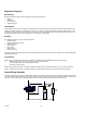
— Do not connect any signal 0V common to ground at the VFD. Ground at the controller end.