
Application Guide


63-7062 40
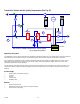
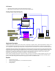
Secondary Chilled Water Pump with DDC Control Option 2 (See Fig. 48)
T
1
M
Inverter
Honeywell
EMC
Controller C1
Primary Chilled Water
V1
Secondary Chilled Water
V1, V2 = Mixing Valve
T
M
V2
T
2
RST
PG
M
O
N
P
A
R
R
E
F
B
T
N
S
RUN READY FAULT
Honeywel
l
Fig. 48. Application diagram.
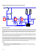
Application
If the existing plant is controlled by Direct Digital Control or connected into a Building Management System, an even more
effective method of controlling the rate of flow of the secondary chilled water pump is available. The bypass port balancing
valves can be set down to a minimum position and the VFD can be set for a low limit speed than will satisfy minimum
requirements. The feedback position from each bypass valve can be used as an input to a control loop. Using a predetermined
setpoint, e.g. 85% open and P+I control, the output from each loop is fed into a load selector (highest signal). The output from
the load selector (equivalent to the AHU with the highest demand) is the input to the VFD. Any increase in valve position above
85% would cause the VFD to increase speed and hence increase the flow rate. Conversely as the AHU with the highest
demand begins to close its valve it would cause the flow to decrease. Hence optimizing the pump flow volumes at all times.
Benefits
— Reduced noise from water pipework.
— Reduced maximum demand.
— Reduced wear and tear on machinery.
— Ability to overspeed the pump to increase capacity.
— Energy-saving on chillers.
— Energy-saving on heat loss through lagging as return water temperature will be higher.
VFD Features Used
— Auto restart.
— Speed search.
— Overspeed.
— Overtorque protection.
— Stall prevention.
— Analog or digital control.
IMPORTANT
Take care with choosing the setpoint for each control loop.