
Application Guide


63-70623
SAFETY
When Installing this Product...
1. Read these instructions carefully. Failure to follow them could damage the product or cause a hazardous condition.
2. Check the ratings given in the instructions and on the product to make sure the product is suitable for your application.
3. Installer must be a trained, experienced service technician.
4. After installation is complete, check out product operation as provided in these instructions.
WARNING
Electrical Shock That Can Cause Death.
Capacitor discharge can produce lethal shock.
Ensure that all circuits are completely safe before commencing work.
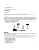
Each VFD has a bank of capacitors that, under normal circumstances, discharges shortly after disconnecting main power (five
or 10 minutes). During normal operation, these capacitors charge to at least 500 Vdc and as high as 800 Vdc.
I
I
n
n
s
s
p
p
e
e
c
c
t
t
i
i
o
o
n
n
P
P
r
r
o
o
c
c
e
e
d
d
u
u
r
r
e
e
IMPORTANT
I
I
n
n
s
s
p
p
e
e
c
c
t
t
i
i
o
o
n
n
a
a
n
n
d
d
R
R
e
e
p
p
a
a
i
i
r
r
a
a
r
r
e
e
o
o
n
n
l
l
y
y
t
t
o
o
b
b
e
e
u
u
n
n
d
d
e
e
r
r
t
t
a
a
k
k
e
e
n
n
b
b
y
y
a
a
c
c
o
o
m
m
p
p
e
e
t
t
e
e
n
n
t
t
p
p
e
e
r
r
s
s
o
o
n
n
.
.
— Most VFD manufacturers include an LED that illuminates whenever the capacitor voltage is above 30 Vdc.
— Do not rely upon these resistors and LED circuits to indicate a safe condition. So far, we have not experienced a failure of
the LED circuit or discharge resistors but this could happen.
The following is the correct procedure to follow:
Test Instruments Required: Standard Multimeter with Vac/Vdc range in excess of 600V.
I
I
M
M
P
P
O
O
R
R
T
T
A
A
N
N
T
T
C
C
h
h
e
e
c
c
k
k
t
t
e
e
s
s
t
t
i
i
n
n
s
s
t
t
r
r
u
u
m
m
e
e
n
n
t
t
s
s
i
i
m
m
m
m
e
e
d
d
i
i
a
a
t
t
e
e
l
l
y
y
p
p
r
r
i
i
o
o
r
r
t
t
o
o
c
c
o
o
m
m
m
m
e
e
n
n
c
c
i
i
n
n
g
g
w
w
o
o
r
r
k
k
b
b
y
y
c
c
o
o
n
n
n
n
e
e
c
c
t
t
i
i
n
n
g
g
t
t
o
o
v
v
o
o
l
l
t
t
a
a
g
g
e
e
s
s
u
u
p
p
p
p
l
l
y
y
.
.
Carry out necessary isolation and safety procedures for working on electrical equipment. Check for compliance with local
requirements. A permit-to-work may be required. Where possible, remove fuses and lock off isolators.
I
I
M
M
P
P
O
O
R
R
T
T
A
A
N
N
T
T
If the LED is illuminated, do not touch any of the internal components of the VFD or associated wiring.
1.
Disconnect power supply from VFD. All indicators, displays, and LED should extinguish after a few seconds.
2.
Wait 5 minutes before taking further action.
3.
Carefully remove any protective covers.
4.
Do not touch any conductors within the VFD.
5.
Confirm that the
LED charge
indicator is illuminated. This LED is bright and cannot be mistaken for another indicator.
6.
If LED indicator is extinguished, identify DC bus circuit and check all busbars and terminals for voltage. Pay particular
attention to terminals marked
P
and
N
.
7.
Ensure that no voltages are present then use the voltage tester to check between conductors and
earth
.
NOTE: The voltage tester can discharge the capacitors by connecting it between busbars/connectors and
earth
.
Monitor the LED
It should be easy to see the level of illumination decay and within 1 or 2 minutes more, the LED should be extinguished. An
LED maintaining illumination level can indicate damaged discharge resistors that create an open circuit. Also, an additional
power supply may have been installed and is still powering the VFD. Carefully check for Vac supplies using the procedure
outlined in the Installation Procedure section.
I
I
M
M
P
P
O
O
R
R
T
T
A
A
N
N
T
T
Recheck with multimeter before commencing work.
NOTE: If no Vac supplies are found, it is probable that discharge resistors are faulty.