
User Guide
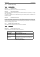
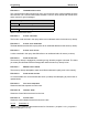
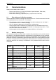
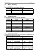
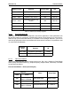
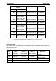
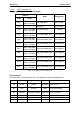
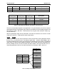
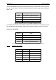
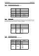
Table Of Contents
- 1. Safety
- 2. Modbus - general info
- 3. Modbus technical data
- 4. Modbus installation
- 5. Programming
- 5.2.1 Ethernet common settings (M5.8.1)
- 5.2.2 Modbus TCP settings (M5.8.2)
- 5.3.1 Modbus RTU Parameters
- 5.3.2 Modbus RTU monitoring values
- 5.4.1 Ethernet common settings
- 5.4.2 Modbus TCP settings
- 5.4.2.1 Common settings
- 5.4.3 Modbus TCP monitoring values
- 5.4.3.1 Connection 1
- 5.4.3.2 Connection 2
- 6.3.1 Coil registers
- 6.3.2 Input discrete registers
- 6.3.3 Holding and input registers
- 6.3.3.1 Drive Application ID’s
- 6.3.3.2 FB Process data IN
- 6.3.3.3 FB Process data OUT
- 6.3.3.4 ID map
- 6.3.3.5 Operation day counter
- 6.3.3.6 Resettable operation day counter
- 6.3.3.7 Energy counter
- 6.3.3.8 Resettable energy counter
- 6.3.3.9 Fault history

Communications Honeywell • 27
Table 20. Status Word bits B1-B28
Table 21. Status Word bits B29-B31, descriptions of bit connections
The use of process data depends on the application. In a typical situation, the device is started
and stopped with the ControlWord (CW) written by the Master and the Rotating speed is set
with Reference (REF). With PD1…PD8 the device can be given other reference values (e.g.
Torque reference).
With the StatusWord (SW) read by the Master, the status of the device can be seen. Actual
Value (ACT) and PD1…PD8 show the other actual values.
6.3.3.4
ID map
Using the ID map, you can read consecutive memory blocks that contain parameters whose
ID's are not in a consecutive order. The address range 10501 - 10530 is called 'IDMap', and it
includes an address map in which you can write your parameter ID's in any order. The address
range 10601 to 10630 is called 'IDMap Read/Write,' and it includes values for parameters writ-
ten in the IDMap. As soon as one ID number has been written in the map cell 10501, the cor-
responding parameter value can be read and written in the address 10601, and so on.
Table 22. IDMap initialization
B6 ZeroSpeed True False Motor running at zero speed
B7 FluxReady True False Motor is magnetized
B8-B28 Not used
B29
Control place
B30
Control place
B31
Control place
Description
00 1 Fieldbus
01 0 Keypad
01 1 PC tool
1 0 0 I/O terminals
Address Data
410501 700
410502 702
410503 707
410504 704
Parameter ID’s
ID
699
700
701
702
703
704
705
706
707
708