
User Guide


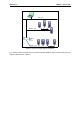


Table Of Contents
- 1. Safety
- 2. Modbus - general info
- 3. Modbus technical data
- 4. Modbus installation
- 5. Programming
- 5.2.1 Ethernet common settings (M5.8.1)
- 5.2.2 Modbus TCP settings (M5.8.2)
- 5.3.1 Modbus RTU Parameters
- 5.3.2 Modbus RTU monitoring values
- 5.4.1 Ethernet common settings
- 5.4.2 Modbus TCP settings
- 5.4.2.1 Common settings
- 5.4.3 Modbus TCP monitoring values
- 5.4.3.1 Connection 1
- 5.4.3.2 Connection 2
- 6.3.1 Coil registers
- 6.3.2 Input discrete registers
- 6.3.3 Holding and input registers
- 6.3.3.1 Drive Application ID’s
- 6.3.3.2 FB Process data IN
- 6.3.3.3 FB Process data OUT
- 6.3.3.4 ID map
- 6.3.3.5 Operation day counter
- 6.3.3.6 Resettable operation day counter
- 6.3.3.7 Energy counter
- 6.3.3.8 Resettable energy counter
- 6.3.3.9 Fault history

Modbus installation Honeywell • 9
Figure 4.
You can use the Modbus communication protocol through Ethernet and RS485.
4.1 Prepare for use through ethernet
Figure 5.
3
Connect the Ethernet cable (see specification on page 7) to its terminal and run
the cable through the conduit as shown in Figure 5.
Ethernet
connector
Ethernet
cable run
conduit
I/O terminal
(see larger
picture)
Grounding
bar
DIP
switches
28 29
12 13 14 15 16 17 18 19 30
BA
RS485
terminals
A = Data- B = Data+
21 22 23 24 25 26
1234567891011
max. 40 mm
Ethernet
cable