
Application Guide


63-706239
IMPORTANT
Very careful calibration of controllers is required to ensure that the chillers are safeguarded under all conditions. The
chillers built-in controllers will still control at their original value. The supply temperature to building will not change.
When starting the second chiller, the isolating valve must be opened as slowly as possible, to prevent the on machine
tripping under low flow condition.
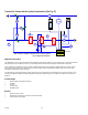
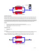
Secondary Chilled Water Pump Option 1 (See Fig. 47)
RST
PG
MON PAR REFBTNS
RUN READY FAULT
Honeywe
ll
T
2
T
1
M M
Inverter
Honeywell
EMC
Controller C1
Primary Chilled Water
V1
Secondary Chilled Water
V1 = Mixing Valve
RST
PG
MONPAR REF BTNS
RUNREADY FAULT
Honeywe
ll
Fig. 47. Application diagram.
Application
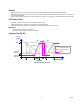
Conventional Control Valve V1 is modulated by controller C1 with sensor T1 located in the secondary chilled water flow. The
objective is to give a constant supply temperature at T1. The return temperature at T2 will vary relative to the load. Only at full
load (hottest period of the year) will the return temperature be at design.
At all times a fixed speed circulating pump supplies the design water volume required to satisfy maximum load conditions.
When full load capacity is not required (for most of the year) energy is continuously being wasted - a more economic system
would be to install a VFD to control the pump circulating rate against the return temperature measured at T2. The controller
setpoint would be the (design full load) return temperature.
As the flow rate is now being varied, the need for the three port valve is reduced, the bypass balancing values can be set down
to a minimum.
Benefits
— Reduced noise from water pipework.
— Reduced maximum demand.
— Reduced wear and tear on machinery.
— Ability to overspeed the pump to increase capacity.
— Energy-saving on chillers.
— Energy-saving on heat loss through lagging. Return water temperature will be higher.