
Application Guide

63-7062 50
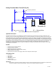
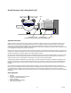
A simple check for stable control from the VFD is to install a temporary control potentiometer, (maybe 15 - 20K ohms in value)
using the VFD power supply, usually 10 or 15 Vdc and 0V (ground). Connect the ends of the potentiometer to the DC power
supply and to 0V ground and connect the wiper of the potentiometer to the voltage speed reference input. Vary the setting of
the potentiometer and monitor the reference value on the VFD display for stability. Also monitor the display whilst the VFD is
driving the motor - again it should be stable.
Where Vac is present on the speed reference lines, several courses of action can be taken:
1. Check for correct shielding and segregation of the control cables.
2. Check that correct input RFI filter has been applied.
3. Check for correct earth grounding on control and power cable shields.
4. Check for malfunction of control instruments.
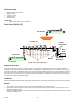
5. Install filters in the reference lines to reduce the amount of Vac present.
6. Some VFDs have software filter options which can be enabled. However, these do cause delay in response and may not
be acceptable.
Faults and Trips
Most VFDs have some form of error indication and an error log. The error indication is usually either on the VFD display, or an
indicator LED (or relay output), or both.
Where an error log exists, it usually has the capacity for logging multiple errors and may also store other details that may have
caused the trip. However, in most cases this information is only available on the last trip that has occurred and then only if the
power has been maintained to the VFD.
Faults causing trips can be in 1 of 2 categories i.e.
minor
or
major
.
Normally resetting the VFD after a minor fault will not cause damage to the VFD or immediate damage to the motor.
Casual resetting of the VFD after a major fault, could cause serious damage to the VFD, and may cause damage to the motor
and or cables between the motor and the VFD.
Examples of Minor faults would be:
— VFD overheat.
— Motor thermal trip.
— Loss of control loop.
— DC bus overvoltage.
— Loss of input phase.
Examples of Major faults would be:
— Instantaneous over current.
— Earth fault.
— Open circuit output phase.
— DC bus fuse open circuit.
Further inspection of the VFD technical manual will show any additional error messages.
Action if the VFD is Tripped
If the display indicates that the DC bus fuse has become open circuit, it is likely that one or more of the output power transistors
have become short circuited or damaged in some way. Casual replacement of the DC bus fuse should not be made without full
internal inspection and testing of power transistors (covered later in document.)
If the VFD is still powered, attempt to call up the motor voltage, motor current, speed, DC bus voltage and any other parameter
available from the VFD. If this monitoring is available, log these parameters before powering down the VFD, as this important
information may be lost. Also, if the VFD is fitted with a cooling fan, check if it is operating correctly.
If the error can be categorized as
minor
, the VFD can be reset. If the error can be categorized as
major
, it should be powered
down at this stage.
Once the DC bus voltage has decayed to a safe level further work can continue.
The VFD should be inspected for internal damage, overheating. If no damage is apparent then the power can be reinstated.
Care should be taken when restoring the power supply, as this will normally reset the trip and if the command to run is still
present on the VFD, it will begin to accelerate the motor.