
Application Guide

63-7062 16
Table 2. Power Factor of Some Devices.
Device Power Factor Device Power Factor
Incandescent Lamp 100% Single Phase Induction Motor 60%-80%
Neon Lamp 40%-50% Three Phase Induction Motor 70%-90%
Fluorescent Lamp (w/Stabilizer) 90% Table Top Fan 60%-80%
Radio 100% Ceiling Fan 50%-60%
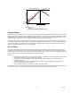
Useful Formulae
Motor speed = (Supply frequency * 120) / Number of motor poles
The above formula provides the synchronous (no load) speed of the motor. However, as load is applied to the motor, it begins
to develop slip. The actual speed deviates from synchronous speed. This can be positive slip or negative slip in order to
develop torque.
Shaft Power in kW = (Nm * RPM) / 9549
Torque in Nm = (9549 * kW) / RPM
COS
φ
(PF) typically 0.8 and efficiency 0.8 for small motors
Electrical Power in kW = (V * I * PF * 1.73) / 1000
VFD FUNDAMENTALS
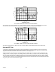
Construction
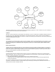
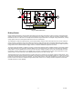
The majority of general purpose VFDs produced today have four fundamental sections (see Fig. 17). These are:
1. The input rectifier or converter.
2. The DC bus.
3. The output stack or VFD.
4. The controller.
The input rectifier or converter can be either three-phase or, in small machines, single phase. This input rectifier converts the
Vac input into Vdc and charges the capacitors in this part of the circuit.
The DC bus acts as a small reservoir for power on which the output VFD draws. If any regenerated energy from the load
remains, it is stored on the DC bus in the capacitors.
The
output stack
or VFD draws power from the DC bus and creates a synthesized Vac power supply, the frequency of which
can be varied by the controller. The output of the converter is used to drive the electric motor.
Supervising the whole machine is a computerized controller, which is capable of making decisions based on the demands and
on state of motor and load. It is driving and taking protective measures to ensure that no damage occurs to the machinery it is
controlling or the VFD itself.