
User Guide
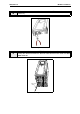
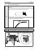
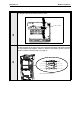
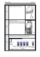
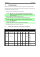
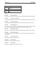

Table Of Contents
- 1. Safety
- 2. Modbus - general info
- 3. Modbus technical data
- 4. Modbus installation
- 5. Programming
- 5.2.1 Ethernet common settings (M5.8.1)
- 5.2.2 Modbus TCP settings (M5.8.2)
- 5.3.1 Modbus RTU Parameters
- 5.3.2 Modbus RTU monitoring values
- 5.4.1 Ethernet common settings
- 5.4.2 Modbus TCP settings
- 5.4.2.1 Common settings
- 5.4.3 Modbus TCP monitoring values
- 5.4.3.1 Connection 1
- 5.4.3.2 Connection 2
- 6.3.1 Coil registers
- 6.3.2 Input discrete registers
- 6.3.3 Holding and input registers
- 6.3.3.1 Drive Application ID’s
- 6.3.3.2 FB Process data IN
- 6.3.3.3 FB Process data OUT
- 6.3.3.4 ID map
- 6.3.3.5 Operation day counter
- 6.3.3.6 Resettable operation day counter
- 6.3.3.7 Energy counter
- 6.3.3.8 Resettable energy counter
- 6.3.3.9 Fault history

Modbus installation Honeywell • 11
4.2 Prepare for use through RTU
Figure 8.
3
Strip about 15 mm of the RS485 cable (see specification on page 7) and cut off
the grey cable shield. Remember to do this for both bus cables (except for the
last device).
Leave no more than 10 mm of the cable outside the terminal block and strip the
cables at about 5 mm to fit in the terminals. See picture below.
Also strip the cable now at such a distance from the terminal that you can fix it to
the frame with the grounding clamp. Strip the cable at a maximum length of 15
mm. Do not strip the aluminum cable shield!
4
Then connect the cable to its appropriate terminals on drive standard terminal
block, terminals A and B (A = negative, B = positive). See Figure 8.
10
5
B
20 A
11
89
10
12
B
13
14
15 16 17 18 19
20 A
1
11
234567
8910
21 22 23 24 25 26
2829
RS485
terminals
(A and B)