
User Guide
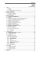


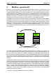
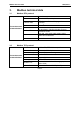

Table Of Contents
- 1. Safety
- 2. Modbus - general info
- 3. Modbus technical data
- 4. Modbus installation
- 5. Programming
- 5.2.1 Ethernet common settings (M5.8.1)
- 5.2.2 Modbus TCP settings (M5.8.2)
- 5.3.1 Modbus RTU Parameters
- 5.3.2 Modbus RTU monitoring values
- 5.4.1 Ethernet common settings
- 5.4.2 Modbus TCP settings
- 5.4.2.1 Common settings
- 5.4.3 Modbus TCP monitoring values
- 5.4.3.1 Connection 1
- 5.4.3.2 Connection 2
- 6.3.1 Coil registers
- 6.3.2 Input discrete registers
- 6.3.3 Holding and input registers
- 6.3.3.1 Drive Application ID’s
- 6.3.3.2 FB Process data IN
- 6.3.3.3 FB Process data OUT
- 6.3.3.4 ID map
- 6.3.3.5 Operation day counter
- 6.3.3.6 Resettable operation day counter
- 6.3.3.7 Energy counter
- 6.3.3.8 Resettable energy counter
- 6.3.3.9 Fault history

Modbus technical data Honeywell • 7
3. Modbus technical data
3.1 Modbus RTU protocol
Table 2.
3.2 Modbus TCP protocol
Table 3.
Connections and
communications
Interface RS-485
Data transfer method RS-485 MS/TP, half-duplex
Transfer cable
STP (Shielded Twisted Pair), type Belden 9841
or similar
Connector
2.5 mm
2
Electrical isolation Functional
Modbus RTU
As described in “Modicon Modbus Protocol
Reference Guide”
Baud rate
300, 600, 1200, 2400, 4800, 9600, 19200,
38400 and 57600 baud
Addresses 1 to 247
Connections and
communications
Interface 100BaseTX, IEEE 802.3 compatible
Data transfer method Ethernet half/full -duplex
Data transfer speed 10/100 MBit/s, autosensing
Protocol Modbus TCP
Connector Shielded RJ45 connector
Cable type CAT5e STP
Modbus TCP
As described in Modbus Messaging Implemen-
tation Guide
Default IP Selectable: Fixed or DHCP (AutoIP)