
Application Guide


63-70629
Sine Wave Supply Voltage to Frequency Relationship
The motor nameplate carries several important parameters: kW or HP, voltage, full-load current, full-load motor speed, and
power supply frequency. Two of these, terminal voltage and power supply frequency are very important as they define the
voltage to frequency ratio for the motor. This creates a constant flux (magnetic field) condition throughout the full speed range
of the motor. The voltage to frequency relationship is a simple linear relationship. For example: If frequency changes from 50
Hz to 25 Hz, the voltage should change from 415V (three phase) to 207 volts. If the motor were connected to any sine wave
supply, with a frequency other than that defined on the nameplate, the correct voltage for this frequency can be determined.
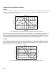
1
2
4
1 Locked Rotor
2 Run Up
3 Pull Out
4 Full Load
Speed
0
100%
0
Tor
qu
e
Slip Speed
Over Load Torque Area
Full Load Torque
3
100%
200%
Fig. 6. Typical motor speed torque curve.
Motor Torque Characteristics
Fig. 7 shows the starting torque characteristics of a typical A/C induction motor. This is a torque curve of a general purpose
motor. There are many other types, depending on load type and performance required. Point 1 is the locked rotor torque,
typically 200% of normal full load torque. As the motor begins to accelerate the load, the torque production ability of the motor
decreases. Then, at point 2, typically 20% of full speed, the torque has fallen to an approximate minimum of 175%. This point is
called the run up point. The torque production ability of the motor increases from the run up point until about 90% speed, point
three, maximum torque, the pull out point, is achieved.
From here, the motor rapidly reaches full load speed, point 4, which corresponds to the nameplate speed on the motor. If the
load is very light, the motor will continue to accelerate to close to the synchronous speed, which in the case of a 4 pole
machine on a 50Hz supply would be 1500 rpm.
NOTE: The difference between the synchronous speed and the full load speed is called
slip.
Slip is generally a few percent of
the synchronous speed, equivalent to 40-50 rpm
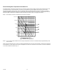
0
0
Cu
rre
nt
Speed
100%
100%
600%
Current Draw for Typical D.O.L. Start with Inverters
Slip
Over Current Area
Inverter
Current
Limit
Inverter
Current
Limit
Fig. 7. Motor Starting Characteristics
When a standard induction motor is switched directly onto a 60 Hz power supply, there is a large inrush of current. This can
exceed six times the motor nameplate full-load current. As the motor accelerates the load, this large current flow falls off rapidly
until a point at which motor speed and load balance. This point is somewhere between no load speed and full load speed. See
Fig. 7. Motors driven by a VFD have the large inrush of current controlled by the VFD. Only under worst case conditions will the
inrush reach 150% of motor nameplate current. However, this setting is adjustable within the VFD and can be limited to a lower
value.