Voyager™ 1200g/1202g Single-Line Laser Bar Code Scanner User’s Guide ™
Disclaimer Honeywell International Inc. (“HII”) reserves the right to make changes in specifications and other information contained in this document without prior notice, and the reader should in all cases consult HII to determine whether any such changes have been made. The information in this publication does not represent a commitment on the part of HII.
Product Agency Compliance - Voyager 1200g USA FCC Part 15 Subpart B Class B This device complies with part 15 of the FCC Rules. Operation is subject to the following two conditions: 1. This device may not cause harmful interference. 2. This device must accept any interference received, including interference that may cause undesired operation. This equipment has been tested and found to comply with the limits for a Class B digital device pursuant to part 15 of the FCC Rules.
Canada Industry Canada ICES-003 This Class B digital apparatus complies with Canadian ICES-003. Operation is subject to the following conditions: 1. This device may not cause harmful interference. 2. This device must accept any interference received, including interference that may cause undesired operation. Conformité à la règlementation canadienne Cet appareil numérique de la Classe B est conforme à la norme NMB-003 du Canada. Son fonctionnement est assujetti aux conditions suivantes : 1.
This product has required the extraction and use of natural resources for its production. It may contain hazardous substances that could impact health and the environment, if not properly disposed. In order to avoid the dissemination of those substances in our environment and to diminish the pressure on the natural resources, we encourage you to use the appropriate take-back systems for product disposal.
South Korea This product meets Korean agency approval. Taiwan If the following label is attached to your product, the product meets Taiwan agency approval: BSMI Standard: CNS13438, CNS 14336 依據標準 : CNS13438, CNS14336 International LED Safety Statement LEDs have been tested and classified as “EXEMPT RISK GROUP” to the standard: IEC 62471:2006. CB Scheme Certified to CB Scheme IEC60950-1, Second Edition. Laser Safety Statement LASER LIGHT: DO NOT STARE INTO BEAM. CLASS 2 LASER PRODUCT.
Embedded Laser Wavelength 645- 660 nm Divergence < 1.5 mrad, per IEC 60825-1 worst case Max power output < 10 mw Caution - use of controls or adjustments or performance of procedures other than those specified herein may result in hazardous radiation exposure. Patents For patent information, please refer to www.honeywellaidc.com/patents. Solids and Water Protection The Voyager 1200g has a rating of IP42, immunity of foreign particles and dripping water.
Product Agency Compliance - Voyager 1202g and CCB00-010BT USA FCC Part 15 Subpart C This device complies with part 15 of the FCC Rules. Operation is subject to the following two conditions: 1. This device may not cause harmful interference. 2. This device must accept any interference received, including interference that may cause undesired operation. Caution: Any changes or modifications made to this equipment not expressly approved by Honeywell may void the FCC authorization to operate this equipment.
C-UL Statement C-UL listed: CSA C22.2 No.60950-1-07, 2nd Edition for I.T.E. product safety. Europe The CE marking on the product indicates that this device is in conformity with all essential requirements of the 1999/5/EC R&TTE Directive. In addition, complies to 2006/95/EC Low Voltage Directive, when shipped with recommended power supply. For further information, contact: Honeywell Imaging & Mobility Europe BV International Inc.
If you need more information on the collection, reuse, and recycling systems, contact your local or regional waste administration. You may also contact your supplier for more information on the environmental performances of this product. Australia/NZ C-Tick Statement Conforms to AS/NZS 3548 EMC requirements. China SRRC Radio Certificate. CCC safety (CCB00-010BT base only) Japan Complies with Technical Regulations Conformity Certification of Specified Radio equipment.
BSMI Standard: CNS13438, CNS14336 (Voyager 1202 only) 依據標準 : CNS13438, CNS14336 NCC standard: Low power frequency electric machineries technical standard: LP0002 International LED Safety Statement LEDs have been tested and classified as “EXEMPT RISK GROUP” to the standard: IEC 62471:2006. Radio Technology Class II CB Scheme Certified to CB Scheme IEC 60950-1, Second Edition. Laser Safety Statement LASER LIGHT: DO NOT STARE INTO BEAM. CLASS 2 LASER PRODUCT. LASERSTRAHLUNG: NICHT IN DEN STRAHL BLICKEN.
Embedded Laser Wavelength 645- 660 nm Divergence < 1.5 mrad, per IEC 60825-1 worst case Max power output < 10 mw Caution - use of controls or adjustments or performance of procedures other than those specified herein may result in hazardous radiation exposure. Patents For patent information, please refer to www.honeywellaidc.com/patents. Solids and Water Protection The Voyager 1202g has a rating of IP42, immunity of foreign particles and dripping water.
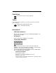
Voyager 1200g Safety Label Locations Laser Output Internal Laser Cautions Compliance Markings information, Part Number, and Serial Number information Compliance Markings information
Voyager 1202g Safety Label Locations Laser Output Internal Laser Cautions Laser Safety Information Compliance Markings information, Part Number, and Serial Number information Compliance Markings information
CCB00-010BT Safety Label Locations Item Number, Serial Number, and Compliance Markings information Compliance Markings information
Table of Contents Chapter 1 - Getting Started About This Manual ...................................................... 1-1 Unpacking Your Device............................................... 1-1 Connecting the Device ................................................ 1-2 Connecting with USB ............................................ 1-2 Connecting with Keyboard Wedge ........................ 1-3 Connecting with RS232 Serial Port ....................... 1-5 Connecting with RS485.............................
Verifone® Ruby Terminal Default Settings ..................2-9 Gilbarco® Terminal Default Settings ............................2-9 Honeywell Bioptic Aux Port Configuration .................2-10 Datalogic™ Magellan© Bioptic Aux Port Configuration ............................................2-10 NCR Bioptic Aux Port Configuration ..........................2-10 Wincor Nixdorf Terminal Default Settings..................2-11 Wincor Nixdorf Beetle™ Terminal Default Settings ...2-12 Keyboard Country Layout .......
Scanner-Bioptic Packet Mode ............................. 2-28 ACK/NAK............................................................. 2-28 Communication Timeout ..................................... 2-28 Chapter 3 - Cordless System Operation How the Charge and Communications Base Works ... 3-1 Linking the Scanner to a Base .................................... 3-1 Communication Between the Cordless System and the Host..............................................................
Charge Only Mode............................................... 3-10 Linked Modes ...................................................... 3-11 Unlinking the Scanner................................................3-11 Override Locked Scanner ..........................................3-12 Out-of-Range Alarm...................................................3-12 Alarm Sound Type ............................................... 3-12 Alarm Duration .....................................................
Beeper Pitch – Good Read ................................... 4-3 Beeper - Transmit Order ....................................... 4-3 Beeper Pitch – Error.............................................. 4-3 Beeper Duration – Good Read.............................. 4-4 Number of Beeps – Good Read ............................ 4-4 Number of Beeps – Error ...................................... 4-4 LED Indicators............................................................. 4-6 LED Settings .........................
Partial Sequence ................................................. 4-21 Require Output Sequence ................................... 4-21 No Read.....................................................................4-22 Chapter 5 - Data Editing Prefix/Suffix Overview..................................................5-1 To Add a Prefix or Suffix: ....................................... 5-1 To Clear One or All Prefixes or Suffixes ................ 5-2 To Add a Carriage Return Suffix to All Symbologies.........
Chapter 7 - Symbologies All Symbologies........................................................... 7-1 Message Length Description....................................... 7-2 Codabar ...................................................................... 7-3 Codabar Concatenation ........................................ 7-4 Code 39....................................................................... 7-7 Code 32 Pharmaceutical (PARAF)........................ 7-9 Full ASCII ....................................
EAN-13 Beginning with 978 Addenda Required ......................................... 7-50 EAN-13 Beginning with 979 Addenda Required ......................................... 7-51 ISBN Translate .................................................... 7-53 ISSN Translate .................................................... 7-54 EAN/JAN-8 ................................................................7-55 MSI ............................................................................7-58 Plessey Code..........
Read Time-Out.................................................... 10-4 Resetting the Standard Product Defaults .................. 10-4 Menu Commands ...................................................... 10-6 Chapter 11 - Product Specifications Voyager 1200g Product Specifications ..................... 11-1 Voyager 1202g Product Specifications ..................... 11-3 CCB00-010BT Product Specifications ...................... 11-4 CCB00-010BT Mounting ...........................................
ASCII Conversion Chart (Code Page 1252) ............... A-4 Code Page Mapping of Printed Barcodes ..................
1 Getting Started About This Manual This User’s Guide provides installation and programming instructions for the Voyager 1200g/1202g linear scanner. Product specifications, dimensions, warranty, and customer support information are also included. Honeywell bar code scanners are factory programmed for the most common terminal and communications settings. If you need to change these settings, programming is accomplished by scanning the bar codes in this guide.
Connecting the Device Connecting with USB A scanner or a base can be connected to the USB port of a computer. 1. Connect the appropriate interface cable to the scanner first, then to the computer. Charge and Communications Base USB Connection: 2. Make sure the cables are secured in the wireways in the bottom of the base and that the base sits flat on a horizontal surface. 3. The scanner beeps.
4. Verify the scanner or base operation by scanning a bar code from the Sample Symbols in the back of this manual. The unit defaults to a USB PC Keyboard. Refer to page 2-5 for other USB terminal settings. For additional USB programming and technical information, refer to “USB Application Note,” available at www.honeywellaidc.com.
Charge and Communications Base Keyboard Wedge Connection: 2. Make sure the cables are secured in the wireways in the bottom of the base and that the base sits flat on a horizontal surface. 3. Turn the terminal/computer power back on. The scanner beeps. 4. Verify the scanner or base operation by scanning a bar code from the Sample Symbols in the back of this manual. The scanner beeps once. The unit defaults to an IBM PC AT and compatibles keyboard wedge interface with a USA keyboard.
Connecting with RS232 Serial Port 1. Turn off power to the terminal/computer. 2. Connect the appropriate interface cable to the scanner. Note: For the scanner or base to work properly, you must have the correct cable for your type of terminal/computer.
3. Make sure the cables are secured in the wireways in the bottom of the base and that the base sits flat on a horizontal surface. 4. Plug the serial connector into the serial port on your computer. Tighten the two screws to secure the connector to the port. 5. Once the scanner or base has been fully connected, power up the computer. This interface programs 9600 baud, 8 data bits, no parity, and 1 stop bit. Connecting with RS485 A scanner or base can be connected for an IBM POS terminal interface. 1.
2. Make sure the cables are secured in the wireways in the bottom of the base and that the base sits flat on a horizontal surface. 3. Turn the terminal/computer power back on. The scanner beeps. 4. Verify the scanner or base operation by scanning a bar code from the Sample Symbols in the back of this manual. The scanner beeps once. For further RS485 settings, refer to RS485, page 2-2.
Setting Custom Defaults You have the ability to create a set of menu commands as your own, custom defaults. To do so, scan the Set Custom Defaults bar code below before each menu command or sequence you want saved. If your command requires scanning numeric codes from the back cover, then a Save code, that entire sequence will be saved to your custom defaults. Scan the Set Custom Defaults code again before the next command you want saved to your custom defaults.
Resetting the Custom Defaults If you want the custom default settings restored to your scanner, scan the Activate Custom Defaults bar code below. This resets the scanner to the custom default settings. If there are no custom defaults, it will reset the scanner to the factory default settings. Any settings that have not been specified through the custom defaults will be defaulted to the factory default settings.
1 - 10
2 Programming the Interface Introduction This chapter describes how to program your system for the desired interface. Programming the Interface - Plug and Play Plug and Play bar codes provide instant scanner set up for commonly used interfaces. Note: After you scan one of the codes, power cycle the host terminal to have the interface in effect. Keyboard Wedge If you want your system programmed for an IBM PC AT and compatibles keyboard wedge interface with a USA keyboard, scan the bar code below.
RS232 Interface RS485 Scan one of the following “Plug and Play” codes to program the scanner for an IBM POS terminal interface. Note: After scanning one of these codes, you must power cycle the cash register.
OPOS Mode The following bar code configures your scanner for OPOS (OLE for Retail Point of Sale) by modifying the following OPOS-related settings: Option Setting Interface Baud Rate RS232 Handshaking RS232 38400 Flow Control, No Timeout XON/XOFF Off ACK/NAK Off 8 Data, 1 Stop, Parity None Data Bits, Stop Bits, and Parity Prefix/Suffix Intercharacter Delay Symbologies Clear All Prefixes and Suffixes Add Code ID and AIM ID Prefix Add CR Suffix Off Enable UPC-A with check digit and number system Enable U
USB IBM SurePos Scan one of the following “Plug and Play” codes to program the scanner for an IBM SurePos (USB handheld scanner) or IBM SurePos (USB tabletop scanner) interface. Note: After scanning one of these codes, you must power cycle the cash register.
USB PC or Macintosh Keyboard Scan one of the following codes to program the scanner for USB PC Keyboard or USB Macintosh Keyboard. Scanning these codes also adds a CR and LF. USB Keyboard (PC) USB Keyboard (Mac) USB Japanese Keyboard (PC) USB HID Scan the following code to program the scanner for USB HID bar code scanners.
Scan the bar code below, then set the length for the HID Fallback (from 060 minutes) by scanning digits from the Programming Chart, then scanning Save. Default = 5 minutes. HID Fallback Mode USB Serial Commands USB Serial Emulation Scan one of the following codes to program the scanner to emulate a regular RS232-based COM Port. If you are using a Microsoft® Windows® PC, you will need to download a driver from the Honeywell website (www.honeywellaidc.com).
ACK/NAK Mode ACK/NAK Mode On * ACK/NAK Mode Off Communication Timeout This allows you to set the length (in milliseconds) for a timeout for the host ACK/NAK response. Scan the bar code below, then set the timeout (from 0-65535 milliseconds) by scanning digits from the Programming Chart, then scanning Save. Default = 2000 ms. Communication Timeout Timeout Retries This setting limits the number of Communication Timeout retries.
Communication Timeout Beeper This selection programs the scanner to issue an error beep when a communication timeout has occurred. The error beep sound is programmed using Number of Beeps – Error (page 4-4). Default = On. Off * On NAK Retries This selection limits the number of NAK retries that can occur in ACK/NAK mode. Scan the bar code below, then set the number of retries (from 0255) by scanning digits from the Programming Chart, then scanning Save. (5 is the recommended setting.
Verifone® Ruby Terminal Default Settings Scan the following Plug and Play code to program the scanner for a Verifone Ruby terminal. This bar code sets the baud rate to 1200 bps and the data format to 8 data bits, Mark parity, 1 stop bit and RTS/CTS no timeout.
Honeywell Bioptic Aux Port Configuration Scan the following Plug and Play code to program the scanner for a Honeywell bioptic scanner auxiliary port configuration. This bar code sets the baud rate to 38400 bps and the data format to 8 data bits, no parity, 1 stop bit. Character RTS/CTS with timeout and 232 ACK/NAK are also enabled.
NCR Bioptic Settings Note: If you are having unexpected results with this programming code, scan the Activate Defaults bar code on page 1-9 first, then scan the programming code above. Wincor Nixdorf Terminal Default Settings Scan the following Plug and Play code to program the scanner for a Wincor Nixdorf terminal. This bar code sets the baud rate to 9600 bps and the data format to 8 data bits, no parity, 1 stop bit.
Wincor Nixdorf Beetle™ Terminal Default Settings Scan the following Plug and Play code to program the scanner for a Wincor Nixdorf Beetle terminal.
Keyboard Country Layout Scan the appropriate country code below to program the keyboard layout for your country or language.
Keyboard Country (continued) Russia Slovenia Spain Switzerland (German) Thailand Turkey Q United Kingdom Vietnam Keyboard Wedge Modifiers ALT Mode If your bar code contains special characters from the extended ASCII chart for example, an e with an accent grave (è), you will use ALT Mode. (See Extended ASCII Characters on page A-5.) Note: Scan the ALT mode bar code after scanning the appropriate Keyboard Country code.
If your keystrokes require using the ALT key and 3 characters, scan the 3 Characters bar code. If your keystrokes require the ALT key and 4 characters, scan the 4 Characters bar code. The data is then output with the special character(s). Default = Off. * Off 3 Characters 4 Characters Keyboard Style This programs keyboard styles, such as Caps Lock and Shift Lock. If you have used Keyboard Conversion settings, they will override any of the following Keyboard Style settings. Default = Regular.
Autocaps via NumLock bar code should be scanned in countries (e.g., Germany, France) where the Caps Lock key cannot be used to toggle Caps Lock. The NumLock option works similarly to the regular Autocaps, but uses the NumLock key to retrieve the current state of the Caps Lock. Autocaps via NumLock Emulate External Keyboard should be scanned if you do not have an external keyboard (IBM AT or equivalent).
Control + ASCII Mode On: The scanner sends key combinations for ASCII control characters for values 00-1F (refer to the ASCII chart for NonPrintable Characters, page A-4). Windows is the preferred mode. All keyboard country codes are supported. DOS mode is a legacy mode, and it does not support all keyboard country codes. New users should use the Windows mode.
between scan codes. Set the length (in milliseconds) for a delay by scanning the bar code below, then setting the delay (from 1-30) by scanning digits from the Programming Chart, then scanning Save. Default = 0 (800 µs). Inter-Scan Code Delay Break Character When your keyboard detects that any key is being pressed, released, or held down, the keyboard sends a packet of information known as a “scan code” to your computer. There are two different types of scan codes: “make codes” and “break codes.
RS232 Modifiers RS232 Baud Rate Baud Rate sends the data from the scanner to the terminal at the specified rate. The host terminal must be set for the same baud rate as the scanner. Default = 9600.
RS232 Word Length: Data Bits, Stop Bits, and Parity Data Bits sets the word length at 7 or 8 bits of data per character. If an application requires only ASCII Hex characters 0 through 7F decimal (text, digits, and punctuation), select 7 data bits. For applications that require use of the full ASCII set, select 8 data bits per character. Default = 8. Stop Bits sets the stop bits at 1 or 2. Default = 1. Parity provides a means of checking character bit patterns for validity. Default = None.
7 Data, 2 Stop, Parity Space 8 Data, 1 Stop, Parity Space 7 Data, 1 Stop, Parity Mark 7 Data, 2 Stop, Parity Mark 8 Data, 1 Stop Parity Mark RS232 Handshaking RS232 Handshaking allows control of data transmission from the scanner using software commands from the host device. RTS/CTS Off: RTS/CTS is turned off so no data flow control is used, but RTS is still active. RTS/CTS Off, RTS Inactive: RTS/CTS is turned off so no data flow control is used and RTS is inactive.
Character-Based Flow Control with Timeout: The scanner asserts RTS when it has a character to send and waits for a delay (see RS232 Timeout on page 2-22) for CTS to be asserted by the host. If the delay time expires and CTS is not asserted, the device transmit buffer is cleared and scanning may resume. Default =RTS/CTS Off (Voyager 1200) RTS/CTS Off, RTS Inactive (Voyager 1202).
XON/XOFF Standard ASCII control characters can be used to tell the scanner to start sending data (XON/XOFF On) or to stop sending data (XON/XOFF Off). When the host sends the XOFF character (DC3, hex 13) to the scanner, data transmission stops. To resume transmission, the host sends the XON character (DC1, hex 11). Data transmission continues where it left off when XOFF was sent. Default = XON/XOFF Off.
Timeout Retries This setting limits the number of Communication Timeout retries. If the Timeout Retries is set to 0, the transmission is terminated after the initial Communication Timeout. Scan the bar code below, then set the number of retries (from 0-255) by scanning digits from the Programming Chart, then scanning Save. (5 is the recommended setting.) Default = 0.
Support BEL/CAN in ACK/NAK This protocol responds to and commands when in ACK/ NAK mode. The scanner sounds an error tone when a command is sent from the host. terminates the transmission. Default = BEL/ CAN Off. BEL/CAN On * BEL/CAN Off RS232 Defaults If you want the custom RS232 default settings restored to your scanner, scan the RS232 Defaults bar code below. This resets the scanner to the custom default settings (see Setting Custom Defaults on page 1-8).
Block Check Character When this selection is set to Transmit, the NCR Block Check Character (BCC) is expected with incoming messages and transmitted with outgoing messages. Default = Transmit. * Transmit Don’t Transmit NCR Prefix This selection allows you to program an NCR-specific prefix. Refer to the ASCII Conversion Chart (Code Page 1252) on page A-4 to find the hex equivalent for the characters you want for the NCR prefix (typically, 02 for STX).
NCR Prefix/Suffix When set to Transmit, both the NCR prefix and suffix are transmitted with bar codes. Usually, prefixes and suffixes are programmed using the Data Editing selections (see Data Editing beginning on page 5-1), however, the following commands override any other prefix/suffix settings. Default = Don’t Transmit.
Scanner-Bioptic Packet Mode Packet Mode On must be scanned to set the scanner’s format so it is compatible with a bioptic scanner. Default = Packet Mode Off. * Packet Mode Off Packet Mode On ACK/NAK After transmitting data, the scanner waits for an ACK character (hex 06) or a NAK character (hex 15) response from the host. If ACK is received, the communications cycle is completed and the scanner looks for more bar codes.
3 Cordless System Operation Note: This chapter applies only to cordless scanning systems. It does not apply to corded scanners. How the Charge and Communications Base Works A cordless charge and communications base provides the link between the cordless scanner and the host system. The base contains an interface assembly and an RF communication module. The RF communication module performs the data exchange between the cordless scanner and the interface assembly.
To determine if your cordless system is set up correctly, scan one of the sample bar codes in the back of this manual. If the scanner provides a single good read beep and the green LED lights, the scanner has successfully linked to the base. If you receive an error tone and the red LED lights, the scanner has not linked to the base. Refer to page 12-5 for troubleshooting information.
tant to noisy RF environments. The Bluetooth Class 2 power level provides a communication range of 33 feet (10m) between the scanner and base, depending on the environment. System Conditions The components of the cordless system interact in specific ways as you associate the scanner with its base, as you move a scanner out of range, or bring a scanner back in range. The following information explains the cordless system operating conditions.
About the Battery There is a danger of explosion if the batteries are incorrectly replaced. Replace the batteries with only the same or equivalent type recommended by the manufacturer. Dispose of used batteries according to the recycle program for batteries as directed by the governing agency for the country where the batteries are to be discarded. ! Power is supplied to the cordless scanner by a rechargeable battery that is integrated in the scanner handle.
The model Voyager 1202g is designed for use with Honeywell battery pack model 100000495 (Li-ion 3.7Vdc, 7.4 watt hour). Place the scanner in the base that is connected to an appropriate power supply. Use only a Listed Limited Power Source (LPS) or Class 2 type power supply with output rated 5 to 5.2Vdc, 1A.
! Caution: Danger of explosion if batteries are incorrectly replaced. Dispose of used batteries according to the recycle program for batteries as directed by the governing agency for the country where the batteries are to be discarded. Proper Disposal of the Battery When the battery has reached the end of its useful life, the battery should be disposed of by a qualified recycler or hazardous materials handler. Do not incinerate the battery or dispose of the battery with general waste materials.
LED Indication Beeper Indication Cause Green Flash Red, blinking 2 beeps Razz or error tone Successful menu change Unsuccessful menu change Base LED Sequences and Meaning The base contains a red LED that indicate the status of the unit and verifies its communication with the host system. The base also has a green LED that indicates the scanner battery charge condition.
Reset Scanner Scanning this bar code reboots the scanner and causes it to relink with the base. Reset Scanner Scanning While in Base Cradle If you want to be able to scan bar codes while the scanner is in the base, scan the following Scanning in Cradle On bar code. If you want to only allow scanning when the scanner is out of the base, scan Scanning in Cradle Off. Default = Scanning in Cradle On.
red LED on the base will remain lit to indicate that Paging Mode is off. (This light will go out when the button is pressed, then back on when it’s released.) Default = Paging Mode On. * Paging Mode On Paging Mode Off Paging Pitch When you press the Page button on the base, the scanner associated with that base will begin beeping (see Page Button on page 3-3). You can set the pitch of the paging beep for the scanner by scanning one of the following bar codes. Default = Low.
Base Address Scan the following bar code to determine the address of the base you are using. Base Address Scanner Modes The Voyager is capable of working with Bluetooth devices other than the CCB00-010BT charge base. Charge Only Mode There may be times when you want to charge your scanner, but not link to the base. For example, if a scanner is linked to a Bluetooth device and you need to charge the scanner, but want to retain your existing link.
Linked Modes Locked Link Mode and Open Link Mode are the link modes that accommodate different applications. Scan the appropriate bar codes included in the Open Link and Locked Link Mode explanations that follow to switch from one mode to another. Default = Open Link Mode. Locked Link Mode - Single Scanner If you link a scanner to a base using the Locked Link Mode, other scanners are blocked from being linked if they are inadvertently placed into the base.
Override Locked Scanner If you need to replace a broken or lost scanner that is linked to a base, scan the following Override Locked Scanner bar code with a new scanner and place that scanner in the base. The locked link will be overridden, the broken or lost scanner’s link with the base will be removed, and the new scanner will be linked. Override Locked Scanner (Single Scanner) Out-of-Range Alarm If your scanner is out range of the base, an alarm sounds from the scanner.
Scanner Power Time-Out Timer Note: Scanner Power Time-out Timer only applies to cordless systems. It does not apply to corded scanners. When there is no activity within a specified time period, the scanner enters low power mode. Scan the appropriate scanner power time-out bar code to change the time-out duration (in seconds). If the scanner is not activated during the timer interval, the scanner goes into power down mode. Whenever the scanner is activated, the timer is reset.
Automatic Batch Mode stores bar code data when the scanner is out of range of the base. The data is automatically transmitted to the base once the scanner is back in range. When the scanner’s buffer space is full, any bar codes scanned generate an error tone. In order to scan bar codes again, the scanner must be moved back into range of the base so data can be transmitted. Inventory Batch Mode stores bar code data, whether or not you are in range of the base.
three times. Using Batch Mode Quantity On and the Quantity Codes (page 3-16), you could output your data as “00003, XYZ” instead. Default = Batch Mode Quantity Off. * Batch Mode Quantity Off Batch Mode Quantity On Entering Quantities Quantity Codes (page 3-16) allow you to enter a quantity for the last item scanned, up to 9999 (default = 1).
Quantity Codes 0 1 2 3 4 5 6 7 8 9 3 - 16
Delete Last Code If you want to delete the last bar code scanned when in Batch Mode, scan Delete Last Code. Delete Last Code Record Counter If you wish to add a record counter to each bar code scanned in Batch Mode, scan Record Counter On. Your batch output would add a sequential number before each bar code, for example: 00001,bar code 1 00002,bar code 2 Default = Record Counter Off.
Batch Mode Output Order When batch data is transmitted, select whether you want that data sent as FIFO (first-in first-out), or LIFO (last-in first-out). Default = Batch Mode FIFO. * Batch Mode FIFO Batch Mode LIFO Clear All Codes After Transmission If you want to clear the scanner’s buffer of all data accumulated in Batch Mode after the data has been transmitted to the host system, scan Clear All Codes After Transmission.
Transmit Records Automatically If you are operating in Inventory Batch Mode (see Inventory Batch Mode on page 3-14), you can transmit all stored data to the host system when the scanner is placed in the base. If you don’t want the records transmitted when the scanner is placed in the base, scan the Don’t Transmit Records Automatically bar code. Default = Don’t Transmit Records Automatically.
Batch Mode Transmit Delay Sometimes when accumulated scans are sent to the host system, the transmission of those scans is too fast for the application to process. To program a transmit delay between accumulated scans, scan one of the following delays. Default = Off. Note: In most cases, a short (250 ms (milliseconds)) delay is ideal, however, longer delays may be programmed. Contact Technical Support (page 13-2) for additional information.
To rename scanners with sequential, numeric names, scan the following bar codes. Scan the Reset code after each name change and wait for the scanner to relink to the base. 0001 0002 0003 0004 0005 0006 0007 Reset You may also scan the following Scanner Name bar code and scan up to 30 numbers and/or letters for the scanner name.
Using the Scanner with Bluetooth Devices The scanner can be used either with the CCB00-010BT charge base or with other Bluetooth devices. Those devices include personal computers and laptops. Scanning the following Non-Base BT Connection bar code allows the scanner to be used with other Bluetooth devices (e.g., PC/laptop). After you scan the Non-Base BT Connection bar code, follow the instructions supplied with your Bluetooth device to locate the scanner and connect to it.
Auto Reconnect Mode Auto Reconnect controls whether or not the scanner automatically begins the relink process when a loss of connection is detected. When the Auto Reconnect On bar code is scanned, the scanner begins the relink process immediately, without user intervention. Default = Auto Reconnect On.
Maximum Link Attempts The Maximum Link Attempts setting controls the number of times the scanner tries to form a connection with a base. During the connection setup process, the scanner transmits in order to search for and connect to a base. In order to prevent continuous transmissions that could interfere with other users of the ISM band, the number of attempts to connect is limited by this setting. After the maximum number of attempts is reached, the scanner will not attempt to reconnect to a base.
Maximum Link Attempts set to 15 Other values at default settings When the scanner goes out of range, 15 attempts are made to link to the base unit. Each attempt consists of approximately 5 seconds of active time followed by 3 seconds of idle time. After 15 cycles (8*15 =120), or about 2 minutes, the scanner stops trying to connect to the base, but retains any bar codes that may have been saved in batch mode. After one hour, the scanner powers off and batch mode data is lost.
3 - 26
4 Input/Output Settings Power Up Beeper The scanner can be programmed to beep when it’s powered up. Scan the Off bar code(s) if you don’t want a power up beep. Default = Power Up Beeper On - Scanner. Power Up Beeper Off Scanner * Power Up Beeper On Scanner Beep on BEL Character You may wish to force the scanner to beep upon a command sent from the host. If you scan the following Beep on BEL On bar code, the scanner will beep every time a BEL character is received from the host.
Good Read and Error Indicators Beeper – Good Read The beeper may be programmed On or Off in response to a good read. Turning this option off, only turns off the beeper response to a good read indication. All error and menu beeps are still audible. Default = Beeper Good Read On. Beeper - Good Read Off * Beeper - Good Read On Beeper Volume – Good Read The beeper volume codes modify the volume of the beep the scanner emits on a good read. Default = High.
Beeper Pitch – Good Read The beeper pitch codes modify the pitch (frequency) of the beep the scanner emits on a good read. Default = Medium. Low (1600 Hz) * Medium (2350 Hz) High (4200 Hz) Beeper - Transmit Order The beeper transmit order determines when the good read beep occurs. The scanner can be set to emit the good read beep either before or after data transmission. Default = Before Transmission.
Beeper Duration – Good Read The beeper duration codes modify the length of the beep the scanner emits on a good read. Default = Normal. * Normal Beep Short Beep Number of Beeps – Good Read The number of beeps of a good read can be programmed from 1 - 9. The same number of beeps will be applied to the beeper and LED in response to a good read. For example, if you program this option to have five beeps, there will be five beeps and five LED flashes in response to a good read.
To change the number of error beeps, scan the following bar code and then scan a digit (1-9) bar code and the Save bar code on the Programming Chart inside the back cover of this manual. Default = 1.
LED Indicators The green and red LEDs can be programmed to be On or Off and at different brightness levels to indicate various scanner states. Use the following bar codes to program the LED indicators. LED Settings Default = Red LED On with Laser, Green LED On with Good Scan.
Red LED On with CTS Green LED On with CTS Red LED On when Battery is Low Green LED On when Battery is Low 4-7
LED Brightness Default = Red High, Green High. Red Off Green Off Red Low Green Low Red Medium Green Medium * Red High * Green High In-Stand and Out-Of-Stand Settings The following settings program the scanner’s behavior when it is either in the stand, or out of the stand (hand-held). Caution: When working with In-Stand and Out-of-Stand settings, enable the settings you want before disabling those you do not want to use.
In-Stand and Out-of-Stand Defaults If you want the In-Stand or Out-of-Stand default settings restored to your scanner, scan the appropriate Defaults bar code below. They reset the scanner to the custom default settings (see Setting Custom Defaults on page 1-8). If there are no custom defaults, it will reset the scanner to the factory default settings. Any settings that have not been specified through the custom defaults will be defaulted to the factory default settings.
Manual Activation Mode In Manual Activation Mode, you must press the button to scan a bar code. The scanner scans until a bar code is read, or until the button is released. Default = Manual Activation Mode On In-Stand, Manual Activation On Outof-Stand.
Manual Activation Laser Timeout - Button Settings You can set a timeout for the length of time the laser remains on and attempting to decode bar codes when the button is held down, and after it is released. Set the length (in milliseconds) for a timeout by scanning one of the following bar codes, then setting the timeout (from 1-65535 milliseconds) by scanning digits from the Programming Chart, then scanning Save.
CodeGate® When CodeGate is On, the button is used to allow decoded data to be transmitted to the host system. The scanner remains on, scanning and decoding bar codes, but the bar code data is not transmitted until the button is pressed. When CodeGate is Off, bar code data is transmitted when it is decoded. Default = CodeGate Off in-Stand, CodeGate On Out-ofStand.
End Object Detection After Good Read After a bar code is successfully detected and read from the scanner, the laser can be programmed either to remain on and scanning, or to turn off. When End Object Detection After Good Read is enabled, the laser turns off and stops scanning after a good read. If you scan Do Not End Object Detection After Good Read, the laser remains on after a good read. Default = End Object Detection After Good Read.
Object Detection Distance When the scanner is in the stand and you are using Object Detection Mode, you can set the distance range for detecting objects. Short sets the scanner to detect objects approximately 5 inches (12.7cm) away from the nose. Long sets it to detect objects approximately 10 inches (25.4cm) away. Default = Short In-Stand, Long Out-of-Stand.
trigger scanning. Scan the following bar code, then use the Programming Chart to read the alphanumeric combination that represents that ASCII character. Scan Save to finish. Activation Character End Character Activation After Good Read After a bar code is successfully detected and read from the scanner, the laser can be programmed either to remain on and scanning, or to turn off. When End Character Activation After Good Read is enabled, the laser turns off and stops scanning after a good read.
Character Deactivation Mode If you have sent a character from the host to trigger the scanner to begin scanning, you can also send a deactivation character to stop scanning. Scan the following On bar code to use character deactivation, then use Deactivation Character (following) to select the character you will send from the host to terminate scanning. Default = Off. * Off On Deactivation Character This sets the character used to terminate scanning when using Character Deactivation Mode.
Reread Delay This sets the time period before the scanner can read the same bar code a second time. Setting a reread delay protects against accidental rereads of the same bar code. Longer delays are effective in minimizing accidental rereads. Use shorter delays in applications where repetitive bar code scanning is required. Default = Medium.
Output Sequence Editor This programming selection allows you to program the scanner to output data (when scanning more than one symbol) in whatever order your application requires, regardless of the order in which the bar codes are scanned. Reading the Default Sequence symbol programs the scanner to the following Universal values. These are the defaults. Be certain you want to delete or clear all formats before you read the Default Sequence symbol.
Output Sequence Example In this example, you are scanning Code 93, Code 128, and Code 39 bar codes, but you want the scanner to output Code 39 1st, Code 128 2nd, and Code 93 3rd, as shown below. Note: Code 93 must be enabled to use this example.
SEQBLKsequence editor start command 62 code identifier for Code 39 0012 A - Code 39 sample length (11) plus CR suffix (1) = 12 41 start character match for Code 39, 41h = “A” FF termination string for first code 6A code identifier for Code 128 0013 B - Code 128 sample length (12) plus CR suffix (1) = 13 42 start character match for Code 128, 42h = “B” FF termination string for second code 69 code identifier for Code 93 0012 C - Code 93 sample length (11) plus CR suffix (1) = 12 43 start
Sequence Match Beeper By default, the scanner beeps when a sequence match is found. If you want the scanner to remain silent, scan the following Sequence Match Beeper Off bar code. Default = Sequence Match Beeper On. Sequence Match Beeper Off * Sequence Match Beeper On Partial Sequence If an output sequence operation is terminated before all your output sequence criteria are met, the bar code data acquired to that point is a “partial sequence.
When the output sequence is Off, the bar code data is output to the host as the scanner decodes it. Default = Off. Required On/Not Required *Off No Read With No Read turned On, the scanner notifies you if a code cannot be read. If using an EZConfig-Scanning Tool Scan Data Window (see page 9-2), an “NR” appears when a code cannot be read. If No Read is turned Off, the “NR” will not appear. Default = Off.
5 Data Editing Prefix/Suffix Overview When a bar code is scanned, additional information is sent to the host computer along with the bar code data. This group of bar code data and additional, user-defined data is called a “message string.” The selections in this section are used to build the user-defined data into the message string. Prefix and Suffix characters are data characters that can be sent before and after scanned data.
symbology to which you want to apply the prefix or suffix. For example, for Code 128, Code ID is “j” and Hex ID is “6A”. Step 3. Scan the 2 hex digits from the Programming Chart inside the back cover of this manual or scan 9, 9 for all symbologies. Step 4. Determine the hex value from the ASCII Conversion Chart (Code Page 1252) on page A-4, for the prefix or suffix you wish to enter. Step 5. Scan the 2 digit hex value from the Programming Chart inside the back cover of this manual. Step 6.
Step 1. Scan the Clear One Prefix or Clear One Suffix symbol. Step 2. Determine the 2 digit Hex value from the Symbology Chart (included in the Symbology Chart, beginning on page A-1) for the symbology from which you want to clear the prefix or suffix. Step 3. Scan the 2 digit hex value from the Programming Chart inside the back cover of this manual or scan 9, 9 for all symbologies. Your change is automatically saved.
Suffix Selections Add Suffix Clear One Suffix Clear All Suffixes Transmit Alternate Extended ASCII Characters You may need to emulate special keyboard functions, such as up or down arrows, Alt/Make or Alt/Break commands, that are not supported in the Extended ASCII Character table. Refer to Alternate Extended ASCII Characters (page 5-5) for a range of keyboard function keys and corresponding decimal and hex characters.
Alternate Extended ASCII Characters DEC HEX Keyboard Function 128 80 129 81 130 82 up arrow ↑ down arrow ↓ right arrow → DEC HEX Keyboard Function 152 98 F9 153 99 F10 154 9A F11 131 83 left arrow ← 155 9B F12 132 133 134 135 136 137 138 139 140 141 142 143 144 145 146 147 148 149 150 151 Insert Delete Home End Page Up Page Down Right ALT Right CTRL Reserved Reserved Numeric Keypad Enter Numeric Keypad / F1 F2 F3 F4 F5 F6 F7 F8 156 157 158 159 160 161 162 163 164 165 166 167 168 169 170 17
Function Code Transmit When this selection is enabled and function codes are contained within the scanned data, the scanner transmits the function code to the terminal. Charts of these function codes are provided in Supported Interface Keys starting on page 8-2. When the scanner is in keyboard wedge mode, the scan code is converted to a key code before it is transmitted. Default = Enable.
Intercharacter, Interfunction, and Intermessage Delays Some terminals drop information (characters) if data comes through too quickly. Intercharacter, interfunction, and intermessage delays slow the transmission of data, increasing data integrity. Intercharacter Delay An intercharacter delay of up to 5000 milliseconds (in 5ms increments) may be placed between the transmission of each character of scanned data.
Next, scan the Character to Trigger Delay bar code, then the 2-digit hex value for the ASCII character that will trigger the delay ASCII Conversion Chart (Code Page 1252) on page A-4. Delay Length Character to Trigger Delay To remove this delay, scan the Delay Length bar code, and set the number of delays to 0. Scan the Save bar code using the Programming Chart inside the back cover of this manual.
Intermessage Delay An intermessage delay of up to 5000 milliseconds (in 5ms increments) may be placed between each scan transmission. Scan the following Intermessage Delay bar code, then scan the number of 5ms delays, and the Save bar code using the Programming Chart inside the back cover of this manual. 1st Scan Transmission 2nd Scan Transmission Intermessage Delay Intermessage Delay To remove this delay, scan the Intermessage Delay bar code, then set the number of delays to 0.
5 - 10
6 Data Formatting Data Format Editor Introduction You may use the Data Format Editor to change the scanner’s output. For example, you can use the Data Format Editor to insert characters at certain points in bar code data as it is scanned. The selections in the following pages are used only if you wish to alter the output. Default Data Format setting = None.
you are programming. (See Primary/Alternate Data Formats on page 6-10 for further information.) Step 3. Terminal Type Refer to Terminal ID Table (page 6-4) and locate the Terminal ID number for your PC. Scan three numeric bar codes on the Programming Chart to program the scanner for your terminal ID (you must enter 3 digits). For example, scan 0 0 3 for an AT wedge. Note: The wildcard for all terminal types is 099. Step 4. Code I.D.
Other Programming Selections Clear One Data Format This deletes one data format for one symbology. If you are clearing the primary format, scan 0 from the Programming Chart inside the back cover of this manual. If you are clearing an alternate format, scan 1, 2, or 3, depending on the format you are clearing. Scan the Terminal Type and Code I.D. (see Symbology Chart on page A-1), and the bar code data length for the specific data format that you want to delete. All other formats remain unaffected.
Terminal ID Table Terminal Model(s) IBM PC/AT and compatibles PS2 Keyboard USB SurePOS Handheld Scanner USB SurePOS Tabletop Scanner True TTL RS232 RS485 USB Serial PC Keyboard Mac Keyboard Japanese Keyboard (PC) HID POS Terminal ID 003 002 128 129 000 000 051 130 124 125 134 131 Data Format Editor Commands Send Commands Send all characters F1 Include in the output message all of the characters from the input message, starting from current cursor position, followed by an insert character.
Send all characters up to a particular character F3 Include in the output message all characters from the input message, starting with the character at the current cursor position and continuing to, but not including, the search character “ss,” followed by an insert character. The cursor is moved forward to the “ss” character. Syntax = F3ssxx where ss stands for the search character’s hex value for its ASCII code, and xx stands for the insert character’s hex value for its ASCII code.
Move the cursor to the beginning F7 Move the cursor to the first character in the input message. Syntax = F7. Move the cursor to the end EA Move the cursor to the last character in the input message. Syntax = EA. Search Commands Search forward for a character F8 Search the input message forward for “xx” character from the current cursor position, leaving the cursor pointing to the “xx” character. Syntax = F8xx where xx stands for the search character’s hex value for its ASCII code.
Search forward for a non-matching character E6 Search the input message forward for the first non-“xx” character from the current cursor position, leaving the cursor pointing to the non-“xx” character. Syntax = E6xx where xx stands for the search character’s hex value for its ASCII code. Refer to the ASCII Conversion Chart (Code Page 1252) on page A-4 for decimal, hex and character codes.
Compare characters FE Compare the character in the current cursor position to the character “xx.” If characters are equal, move the cursor forward one position. Syntax = FExx where xx stands for the comparison character’s hex value for its ASCII code. Refer to the ASCII Conversion Chart (Code Page 1252) on page A-4 for decimal, hex and character codes. Compare string B2 Compare the string in the input message to the string “s.” If the strings are equal, move the cursor forward past the end of the string.
Data Formatter On, Not Required, Drop Prefix/Suffix Scanned data is modified according to your data format. If a data format is found for a particular symbol, those prefixes and suffixes are not transmitted. Data Format Required, Keep Prefix/Suffix Scanned data is modified according to your data format, and prefixes and suffixes are transmitted. Any data that does not match your data format requirements generates an error tone and the data in that bar code is not transmitted.
will sound. If you wish to hear the error tone when a non-matching bar code is found, scan the Data Format Non-Match Error Tone On bar code. Default = Data Format Non-Match Error Tone On. * Data Format Non-Match Error Tone On Data Format Non-Match Error Tone Off Primary/Alternate Data Formats You can save up to four data formats, and switch between these formats. Your primary data format is saved under 0. Your other three formats are saved under 1, 2, and 3.
For example, you may have set your device to the data format you saved as Data Format 3. You can switch to Data Format 1 for a single button press by scanning the following Single Scan-Data Format 1 bar code. The next bar code that is scanned uses Data Format 1, then reverts back to Data Format 3.
6 - 12
7 Symbologies This programming section contains the following menu selections. Refer to Chapter 10 for settings and defaults.
Message Length Description You are able to set the valid reading length of some of the bar code symbologies. If the data length of the scanned bar code doesn’t match the valid reading length, the scanner will issue an error tone. You may wish to set the same value for minimum and maximum length to force the scanner to read fixed length bar code data. This helps reduce the chances of a misread. EXAMPLE: Decode only those bar codes with a count of 9-20 characters. Min. length = 09Max.
Codabar Codabar On/Off * On Off Codabar Start/Stop Characters Start/Stop characters identify the leading and trailing ends of the bar code. You may either transmit, or not transmit Start/Stop characters. Default = Don’t Transmit. Transmit * Don’t Transmit Codabar Check Character Codabar check characters are created using different “modulos.” You can program the scanner to read only Codabar bar codes with Modulo 16, Modulo 7 CD, or CLSI check characters.
When Check Character is set to Validate, but Don’t Transmit, the unit will only read Codabar bar codes printed with a check character, but will not transmit the check character with the scanned data. * No Check Character Validate Modulo 16, but Don’t Transmit Validate Modulo 16 and Transmit Validate Modulo 7 CD, but Don’t Transmit Validate Modulo 7 CD and Transmit Validate CLSI, but Don’t Transmit Validate CLSI and Transmit Codabar Concatenation Codabar supports symbol concatenation.
Select Require to prevent the scanner from decoding a single “D” Codabar symbol without its companion. This selection has no effect on Codabar symbols without Stop/Start D characters. On * Off Require Concatenation Timeout When searching for bar codes during concatenation, you may wish to set a delay used to find the next bar code.
Codabar Message Length Scan the following bar codes to change the message length. Refer to Message Length Description (page 7-2) for additional information. Minimum and Maximum lengths = 1-80. Minimum Default = 3, Maximum Default = 80.
Code 39 < Default All Code 39 Settings > Code 39 On/Off * On Off Code 39 Start/Stop Characters Start/Stop characters identify the leading and trailing ends of the bar code. You may either transmit, or not transmit Start/Stop characters. Default = Don’t Transmit. Transmit * Don’t Transmit Code 39 Check Character No Check Character indicates that the scanner reads and transmits bar code data with or without a check character.
When Check Character is set to Validate and Transmit, the scanner only reads Code 39 bar codes printed with a check character, and will transmit this character at the end of the scanned data. Default = No Check Character. * No Check Character Validate, but Don’t Transmit Validate and Transmit Code 39 Redundancy If you are encountering errors when reading Code 39 bar codes, you may want to adjust the redundancy count.
Code 32 Pharmaceutical (PARAF) Code 32 Pharmaceutical is a form of the Code 39 symbology used by Italian pharmacies. This symbology is also known as PARAF. On * Off Full ASCII If Full ASCII Code 39 decoding is enabled, certain character pairs within the bar code symbol will be interpreted as a single character. For example: $V will be decoded as the ASCII character SYN, and /C will be decoded as the ASCII character #. Default = Off.
Character pairs /M and /N decode as a minus sign and period respectively. Character pairs /P through /Y decode as 0 through 9.
Interleaved 2 of 5 < Default All Interleaved 2 of 5 Settings > Interleaved 2 of 5 On/Off * On Off Follett Formatting * Off On NULL Characters Interleaved 2 of 5 requires an even number of characters. When an odd number of characters is present, it is due to NULL characters embedded in the bar code. Scan the On bar code below to decode this type of Interleaved 2 of 5 bar code. Default = Off.
Check Digit No Check Digit indicates that the scanner reads and transmits bar code data with or without a check digit. When Check Digit is set to Validate, but Don’t Transmit, the unit only reads Interleaved 2 of 5 bar codes printed with a check digit, but will not transmit the check digit with the scanned data. When Check Digit is set to Validate and Transmit, the scanner only reads Interleaved 2 of 5 bar codes printed with a check digit, and will transmit this digit at the end of the scanned data.
Interleaved 2 of 5 Message Length Scan the bar codes below to change the message length. Refer to Message Length Description (page 7-2) for additional information. Minimum and Maximum lengths = 1-80. Minimum Default = 6, Maximum Default = 80. Minimum Message Length Maximum Message Length NEC 2 of 5 < Default All NEC 2 of 5 Settings > NEC 2 of 5 On/Off On * Off Check Digit No Check Digit indicates that the scanner reads and transmits bar code data with or without a check digit.
When Check Digit is set to Validate and Transmit, the scanner only reads NEC 2 of 5 bar codes printed with a check digit, and will transmit this digit at the end of the scanned data. Default = No Check Digit. * No Check Digit Validate, but Don’t Transmit Validate and Transmit NEC 2 of 5 Redundancy If you are encountering errors when reading NEC 2 of 5 bar codes, you may want to adjust the redundancy count.
Code 93 < Default All Code 93 Settings > Code 93 On/Off * On Off Code 93 Redundancy If you are encountering errors when reading Code 93 bar codes, you may want to adjust the redundancy count. Redundancy adjusts the number of times a bar code is decoded before transmission, which may reduce the number of errors. Note that the higher the redundancy count, the longer it will take to decode the bar code.
Code 93 Message Length Scan the bar codes below to change the message length. Refer to Message Length Description (page 7-2) for additional information. Minimum and Maximum lengths = 1-80. Minimum Default = 3, Maximum Default = 80.
scan a redundancy count between 0 and 10 on the Programming Chart inside the back cover of this manual. Then scan the Save bar code. Default = 0. Straight 2 of 5 Industrial Redundancy Straight 2 of 5 Industrial Message Length Scan the bar codes below to change the message length. Refer to Message Length Description (page 7-2) for additional information. Minimum and Maximum lengths = 1-80. Minimum Default = 3, Maximum Default = 80.
Straight 2 of 5 IATA (two-bar start/stop) Note: This symbology is also known as Airline Code 5. Straight 2 of 5 IATA On/Off On * Off Straight 2 of 5 IATA Redundancy If you are encountering errors when reading Straight 2 of 5 IATA bar codes, you may want to adjust the redundancy count. Redundancy adjusts the number of times a bar code is decoded before transmission, which may reduce the number of errors.
Straight 2 of 5 IATA Message Length Scan the bar codes below to change the message length. Refer to Message Length Description (page 7-2) for additional information. Minimum and Maximum lengths = 1-80. Minimum Default = 13, Maximum Default = 15.
When Check Character is set to Validate and Transmit, the scanner only reads Matrix 2 of 5 bar codes printed with a check character, and will transmit this character at the end of the scanned data. Default = No Check Character. * No Check Character Validate, but Don’t Transmit Validate and Transmit Matrix 2 of 5 Redundancy If you are encountering errors when reading Matrix 2 of 5 bar codes, you may want to adjust the redundancy count.
Code 11 Code 11 On/Off On * Off Check Digits Required These options set whether 1 or 2 check digits are required with Code 11 bar codes. Auto Select Check Digits determines the number of check digits based on the length of the bar code. If the bar code is 10 digits or more, 2 check digits are required. If it is 9 digits or less, 1 check digit is required. The check digit data is only transmitted if you program that feature (see Check Digit Validation on page 7-22).
Check Digit Validation When Check Character is set to Validate and Transmit, the scanner will only read Code 11 bar codes printed with the specified type check character(s), and will transmit the character(s) at the end of the scanned data. Validate and Transmit One Check Digit Validate and Transmit Two Check Digits Validate and Transmit Auto Select Check Digits Code 11 Redundancy If you are encountering errors when reading Code 11 bar codes, you may want to adjust the redundancy count.
Code 11 Message Length Scan the bar codes below to change the message length. Refer to Message Length Description (page 7-2) for additional information. Minimum and Maximum lengths = 1-80. Minimum Default = 3, Maximum Default = 80.
Code 128 Code 128 On/Off * On Off 128 Group Separator Output If you wish to transmit the group separator characters “GS” (0x1D hex) with your Code 128 bar code output, scan the On bar code. When Off is scanned, the group separator is not output. Default =Off. On * Off Code 128 Redundancy If you are encountering errors when reading Code 128 bar codes, you may want to adjust the redundancy count.
128 Redundancy bar code below, then scan a redundancy count between 0 and 10 on the Programming Chart inside the back cover of this manual. Then scan the Save bar code. Default = 0. Code 128 Redundancy Code 128 Message Length Scan the bar codes below to change the message length. Refer to Message Length Description (page 7-2) for additional information. Minimum and Maximum lengths = 1-80. Minimum Default = 3, Maximum Default = 80.
Concatenation Timeout When searching for bar codes during concatenation, you may wish to set a delay used to find the next bar code. Set the length (in milliseconds) for this delay by scanning the bar code below, then setting the timeout (from 165535 milliseconds) by scanning digits from the Programming Chart, then scanning Save. Default = 750. Concatenation Timeout ISBT 128 Predefined Concatenation Sequences Note: You must enable Code 128 and ISBT 128 to use this feature.
ISBT 128 Predefined Concatenation Sequences On/ Off The following selections allow you to enable or require the Predefined ISBT 128 Concatenation Sequences. If you scan Off, the predefined concatenation sequences are disabled. If you scan the Allow Predefined Sequence code, then the scanner will output only the data combination specified in the predefined concatenation sequence you selected.
Step 1. Scan the 1st Left Identifier bar code, below. Step 2. Use the Programming Chart to scan 3, D (hex for “=”). Step 3. Scan Save. Step 4. Scan the 2nd Left Identifier bar code, below. Step 5. Use the Programming Chart to scan 4, 7 (hex for “G”). Step 6. Scan Save. Step 7. Scan the 1st Right Identifier bar code, below. Step 8. Use the Programming Chart to scan 3, D (hex for “=”). Step 9. Scan Save. Step 10. Scan the 2nd Right Identifier bar code, below. Step 11.
If you scan the Require User-Defined Sequence code, the data combination specified in the User-Defined concatenation sequence is required to transmit the data. No data is output unless the sequence is read. Default = Off.
cation Number identifiers, only the first ID character is removed from the Donation Identification Number. The second character is transmitted as normal data. Default = On. * On Off Flag Digit Conversion Type 3 flag digits are a part of the Donation Identification Number in an ISBT 128 bar code. If you select On, the flag data is converted into a single MOD (37, 2) character and transmitted with the bar code data. Scan Off if you do not want the flag digits transmitted. Default = Off.
GS1-128 GS1-128 On/Off * On Off GS1-128 Application Identifier Parsing This allows a single GS1-128 bar code to be broken into multiple transmissions based on the presence of application identifiers (AI) embedded in the bar code. Scan Transmit Without Identifiers if you want the bar code broken into packets and stripped of the AI. If you want the AI included, scan Transmit With Identifiers. Default = Off.
128 Redundancy bar code below, then scan a redundancy count between 0 and 10 on the Programming Chart inside the back cover of this manual. Then scan the Save bar code. Default = 0. GS1-128 Redundancy GS1-128 Message Length Scan the bar codes below to change the message length. Refer to Message Length Description (page 7-2) for additional information. Minimum and Maximum lengths = 1-80. Minimum Default = 3, Maximum Default = 80.
Telepen Telepen On/Off On * Off Telepen Output Using AIM Telepen Output, the scanner reads symbols with start/stop pattern 1 and decodes them as standard full ASCII (start/stop pattern 1). When Original Telepen Output is selected, the scanner reads symbols with start/stop pattern 1 and decodes them as compressed numeric with optional full ASCII (start/stop pattern 2). Default = AIM Telepen Output.
Telepen Redundancy bar code below, then scan a redundancy count between 0 and 10 on the Programming Chart inside the back cover of this manual. Then scan the Save bar code. Default = 0. Telepen Redundancy Telepen Message Length Scan the bar codes below to change the message length. Refer to Message Length Description (page 7-2) for additional information. Minimum and Maximum lengths = 1-80. Minimum Default = 3, Maximum Default = 80.
UPC-A UPC-A On/Off * On Off UPC-A Number System and Check Digit UPC-A sample showing the number system and check digit: Number System Check Digit UPC-A Number System The numeric system digit of a U.P.C. symbol is normally transmitted at the beginning of the scanned data, but the can be programmed so it will not transmit it. Default = On.
UPC-A Check Digit This selection allows you to specify whether the check digit should be transmitted at the end of the scanned data or not. Default = On. * On Off UPC-A Addenda This selection adds 2 or 5 digits to the end of all scanned UPC-A data. Default = Off for both 2 Digit and 5 Digit Addenda. 2 Digit Addenda On * 2 Digit Addenda Off 5 Digit Addenda On * 5 Digit Addenda Off UPC-A Addenda Required When Required is scanned, the scanner will only read UPC-A bar codes that have addenda.
Addenda Timeout You can set a time during which the scanner looks for an addenda. If an addenda is not found within this time period, the data can be either transmitted or discarded, based on the setting you are using for UPC-A Addenda Required (see page 7-36). Set the length (in milliseconds) for this timeout by scanning the bar code below, then setting the timeout (from 065535 milliseconds) by scanning digits from the Programming Chart, then scanning Save. Default = 100.
UPC-A/EAN-13 with Extended Coupon Code Use the following codes to enable or disable UPC-A and EAN-13 with Extended Coupon Code. When left on the default setting (Off), the scanner treats Coupon Codes and Extended Coupon Codes as single bar codes. If you scan the Allow Concatenation code, when the scanner sees the coupon code and the extended coupon code in a single scan, it transmits both as separate symbologies. Otherwise, it transmits the first coupon code it reads.
Default = Don’t Require Coupon Code. * Don’t Require Coupon Code Require Coupon Code UPC-A Number System 5 Addenda Required This setting programs the scanner to require any combination of a coupon code, a 2 digit addenda, or a 5 digit addenda on UPC-A bar codes that begin with a “5.” The following settings can be programmed: Require Coupon Code/Addenda: All UPC-A bar codes that begin with a “5” must have a coupon code, a 2 digit addenda, a 5 digit addenda, or a combination of these addenda.
Default = Don’t Require Coupon Code/Addenda. * Don’t Require Coupon Code/ Addenda Require 2 Digit Addenda Require 5 Digit Addenda Require 2 or 5 Digit Addenda Require Coupon Code Require Coupon Code or 2 Digit Addenda Require Coupon Code or 5 Digit Addenda Require Coupon Code, 2 Digit Addenda, or 5 Digit Addenda Addenda Timeout You can set a time during which the scanner looks for a coupon code.
scanning the bar code below, then setting the timeout (from 0-65535 milliseconds) by scanning digits from the Programming Chart, then scanning Save. Default = 100. Note: The Addenda Timeout setting is applied to all addenda and coupon code searches. Addenda Timeout UPC-E0 UPC-E0 On/Off Most U.P.C. bar codes lead with the 0 number system. To read these codes, use the UPC-E0 On selection.
UPC-E0 Number System The numeric system digit of a UPC-A symbol is normally transmitted at the beginning of scanned data. When using UPC-E Expand, the unit can be programmed so it will not transmit it. Default = On. * On Off UPC-E0 Number System and Check Digit UPC-E0 sample showing the number system and check digit: Number System Check Digit UPC-E0 Check Digit Check Digit specifies whether the check digit should be transmitted at the end of the scanned data or not. Default = Off.
UPC-E0 Leading Zero This feature allows the transmission of a leading zero (0) at the beginning of scanned data. To prevent transmission, scan Off. Default = Off. On * Off UPC-E0 Addenda This selection adds 2 or 5 digits to the end of all scanned UPC-E data. Default = Off for both 2 Digit and 5 Digit Addenda. 2 Digit Addenda On * 2 Digit Addenda Off 5 Digit Addenda On * 5 Digit Addenda Off UPC-E0 Addenda Required When Required is scanned, the scanner will only read UPC-E bar codes that have addenda.
Addenda Timeout You can set a time during which the scanner looks for an addenda. If an addenda is not found within this time period, the data can be either transmitted or discarded, based on the setting you are using for UPC-E0 Addenda Required (page 7-43). Set the length (in milliseconds) for this timeout by scanning the bar code below, then setting the timeout (from 065535 milliseconds) by scanning digits from the Programming Chart, then scanning Save. Default = 100.
EAN/JAN-13 EAN/JAN-13 On/Off * On Off EAN/JAN-13 Check Digit This selection allows you to specify whether the check digit should be transmitted at the end of the scanned data or not. Default = On.
EAN/JAN-13 Addenda This selection adds 2 or 5 digits to the end of all scanned EAN/JAN-13 data. Default = Off for both 2 Digit and 5 Digit Addenda. 2 Digit Addenda On * 2 Digit Addenda Off 5 Digit Addenda On * 5 Digit Addenda Off EAN/JAN-13 Addenda Required When Required is scanned, the scanner will only read EAN/JAN-13 bar codes that have addenda. Default = Not Required.
Don’t Require 2 Digit Addenda: If you have selected Require 2 Digit Addenda, and you want to disable this feature, scan Don’t Require 2 Digit Addenda. EAN-13 bar codes are transmitted, depending on the setting you are using for EAN/JAN-13 Addenda Required. Default = Don’t Require 2 Digit Addenda. * Don’t Require 2 Digit Addenda Require 2 Digit Addenda EAN-13 Beginning with 290 Addenda Required This setting programs the scanner to require a 5 digit addenda only on EAN-13 bar codes that begin with “290.
Require Addenda: All EAN-13 bar codes that begin with a “378” or “379” must have a 2 digit addenda, a 5 digit addenda, or a combination of these addenda. The EAN-13 bar code with the addenda is then transmitted as a single, concatenated bar code. If the required addenda is not found within the Addenda Timeout period, the EAN-13 bar code is discarded. Don’t Require Addenda: If you have selected Require Addenda, and you want to disable this feature, scan Don’t Require Addenda.
Default = Don’t Require Addenda. * Don’t Require Addenda Require 2 Digit Addenda Require 5 Digit Addenda Require 2 or 5 Digit Addenda EAN-13 Beginning with 434/439 Addenda Required This setting programs the scanner to require any combination of a 2 digit addenda or a 5 digit addenda on EAN-13 bar codes that begin with a “434” or “439.
Default = Don’t Require Addenda. * Don’t Require Addenda Require 2 Digit Addenda Require 5 Digit Addenda Require 2 or 5 Digit Addenda EAN-13 Beginning with 977 Addenda Required This setting programs the scanner to require a 2 digit addenda only on EAN-13 bar codes that begin with “977.” The following settings can be programmed: Require 2 Digit Addenda: All EAN-13 bar codes that begin with “977” must have a 2 digit addendum.
Require 5 Digit Addenda: All EAN-13 bar codes that begin with “978” must have a 5 digit addendum. The EAN-13 bar code with the 5 digit addendum is then transmitted as a single, concatenated bar code. If a 5 digit addendum is not found within the Addenda Timeout period, the EAN13 bar code is discarded. Don’t Require 5 Digit Addenda: If you have selected Require 5 Digit Addenda, and you want to disable this feature, scan Don’t Require 5 Digit Addenda.
Addenda Timeout You can set a time during which the scanner looks for an addenda. If an addenda is not found within this time period, the data can be either transmitted or discarded, based on the setting you are using for EAN/JAN-13 Addenda Required. Set the length (in milliseconds) for this timeout by scanning the bar code below, then setting the timeout (from 0-65535 milliseconds) by scanning digits from the Programming Chart, then scanning Save. Default = 100.
ISBN Translate ISBNs are printed on books using the EAN-13 bar code symbology. To translate EAN-13 Bookland symbols into their equivalent ISBN number format, scan the On bar code below. Default = Off. On * Off Convert ISBN to 13-Digit When translating EAN-13 codes to the ISBN format, you can convert the bar code to a 13 digit format by scanning the Convert to 13-Digit On bar code below. Default = Convert to 13-Digit Off.
ISSN Translate When On is scanned, EAN-13 977 Bookland symbols are translated into their equivalent 8-digit ISSN number format. For example, 9770123456787 will be transmitted as 01234560. Default = Off. On * Off ISSN Reformat When Reformat On is scanned, EAN-13 977 Bookland symbols are translated into their equivalent 8-digit ISSN number format, with hyphens added to the output. For example, 9770123456787 will be transmitted as 0123-456-0.
EAN/JAN-8 EAN/JAN-8 On/Off * On Off EAN/JAN-8 Check Digit This selection allows you to specify whether the check digit should be transmitted at the end of the scanned data or not. Default = On.
EAN/JAN-8 Addenda This selection adds 2 or 5 digits to the end of all scanned EAN/JAN-8 data. Default = Off for both 2 Digit and 5 Digit Addenda. 2 Digit Addenda On * 2 Digit Addenda Off 5 Digit Addenda On * 5 Digit Addenda Off EAN/JAN-8 Addenda Required When Required is scanned, the scanner will only read EAN/JAN-8 bar codes that have addenda. Default = Not Required. Required * Not Required Addenda Timeout You can set a time during which the scanner looks for an addenda.
scanning the bar code below, then setting the timeout (from 0-65535 milliseconds) by scanning digits from the Programming Chart, then scanning Save. Default = 100. Note: The Addenda Timeout setting is applied to all addenda and coupon code searches. Addenda Timeout EAN/JAN-8 Addenda Separator When this feature is On, there is a space between the data from the bar code and the data from the addenda. When turned Off, there is no space. Default = Off.
MSI MSI On/Off On * Off MSI Check Character Different types of check characters are used with MSI bar codes. You can program the scanner to read MSI bar codes with Type 10 check characters. Default = Validate Type 10, but Don’t Transmit. When Check Character is set to Validate Type 10 and Transmit, the scanner will only read MSI bar codes printed with the specified type check character(s), and will transmit the character(s) at the end of the scanned data.
When Check Character is set to Validate Type 10, but Don’t Transmit, the unit will only read MSI bar codes printed with the specified type check character(s), but will not transmit the check character(s) with the scanned data.
MSI Message Length Scan the bar codes below to change the message length. Refer to Message Length Description (page 7-2) for additional information. Minimum and Maximum lengths = 1-80. Minimum Default = 3, Maximum Default = 80. Minimum Message Length Maximum Message Length Plessey Code < Default All Plessey Code Settings > Plessey Code On/Off On * Off Plessey Check Character No Check Character indicates that the scanner reads and transmits bar code data with or without a check character.
When Check Character is set to Validate and Transmit, the scanner only reads Plessey bar codes printed with a check character, and will transmit this character at the end of the scanned data. Default = No Check Character. * No Check Character Validate, but Don’t Transmit Validate and Transmit Plessey Redundancy If you are encountering errors when reading Plessey bar codes, you may want to adjust the redundancy count.
GS1 DataBar Omnidirectional < Default All GS1 DataBar Omnidirectional Settings > GS1 DataBar Omnidirectional On/Off * On Off GS1 DataBar Omnidirectional Redundancy If you are encountering errors when reading GS1 DataBar Omnidirectional bar codes, you may want to adjust the redundancy count. Redundancy adjusts the number of times a bar code is decoded before transmission, which may reduce the number of errors. Note that the higher the redundancy count, the longer it will take to decode the bar code.
GS1 DataBar Limited < Default All GS1 DataBar Limited Settings > GS1 DataBar Limited On/Off * On Off GS1 DataBar Limited Redundancy If you are encountering errors when reading GS1 DataBar Limited bar codes, you may want to adjust the redundancy count. Redundancy adjusts the number of times a bar code is decoded before transmission, which may reduce the number of errors. Note that the higher the redundancy count, the longer it will take to decode the bar code.
GS1 DataBar Expanded < Default All GS1 DataBar Expanded Settings > GS1 DataBar Expanded On/Off * On Off GS1 DataBar Expanded Redundancy If you are encountering errors when reading GS1 DataBar Expanded bar codes, you may want to adjust the redundancy count. Redundancy adjusts the number of times a bar code is decoded before transmission, which may reduce the number of errors. Note that the higher the redundancy count, the longer it will take to decode the bar code.
GS1 DataBar Expanded Message Length Scan the bar codes below to change the message length. Refer to Message Length Description (page 7-2) for additional information. Minimum and Maximum lengths = 1-80. Minimum Default = 3, Maximum Default = 80. Minimum Message Length Maximum Message Length Trioptic Code Trioptic Code is used for labeling magnetic storage media.
If EAN8 to EAN13 Conversion is scanned, all EAN8 bar codes are converted to EAN13 format. Default = GS1 Emulation Off. GS1-128 Emulation GS1 DataBar Emulation GS1 Code Expansion Off EAN8 to EAN13 Conversion * GS1 Emulation Off Postal Codes The following lists linear postal codes. Any combination of linear postal code selections can be active at a time.
China Post (Hong Kong 2 of 5) On/Off On * Off China Post (Hong Kong 2 of 5) Redundancy If you are encountering errors when reading China Post (Hong Kong 2 of 5) bar codes, you may want to adjust the redundancy count. Redundancy adjusts the number of times a bar code is decoded before transmission, which may reduce the number of errors. Note that the higher the redundancy count, the longer it will take to decode the bar code.
7 - 68
8 Interface Keys Keyboard Function Relationships The following Keyboard Function Code, Hex/ASCII Value, and Full ASCII “CTRL”+ relationships apply to all terminals that can be used with the scanner. Refer to page 2-17 enable Control + ASCII mode.
The last five characters in the Full ASCII “CTRL”+ column ( [ \ ] 6 - ), apply to US only. The following chart indicates the equivalents of these five characters for different countries. Note: Not all countries may be supported by your device. Country Codes United States [ \ ] 6 - Belgium [ < ] 6 - Scandinavia 8 < 9 6 - France ^ 8 $ 6 = Germany à + 6 - Italy \ + 6 - Switzerland < ..
ASCII HEX CR SO SI DLE DC1 DC2 DC3 DC4 NAK SYN ETB CAN EM SUB ESC FS GS RS US DEL 0D 0E 0F 10 11 12 13 14 15 16 17 18 19 1A 1B 1C 1D 1E 1F 7F IBM AT/XT and PS/2 Compatibles, WYSE PC/AT Supported Keys CR/Enter Insert Escape F11 Home Print Back Space Back Tab F12 F1 F2 F3 F4 F5 F6 F7 F8 F9 F10 Apple Mac/iMac Supported Keys RETURN Ins Help ESC F11 Home Prnt Scrn BACKSPACE LSHIFT TAB F12 F1 F2 F3 F4 F5 F6 F7 F8 F9 F10 BACKSPACE 8-3
8-4
9 Utilities To Add a Test Code I.D. Prefix to All Symbologies This selection allows you to turn on transmission of a Code I.D. before the decoded symbology. (See the Symbology Chart, beginning on page A-1) for the single character code that identifies each symbology.) This action first clears all current prefixes, then programs a Code I.D. prefix for all symbologies. This is a temporary setting that will be removed when the unit is power cycled. Add Code I.D.
Test Menu When you scan the Test Menu On code, then scan a programming code in this manual, the scanner displays the content of a programming code. The programming function will still occur, but in addition, the content of that programming code is output to the terminal. Note: This feature should not be used during normal scanner operation.
item under the “Configure” tree node in the application explorer. When one of these tree nodes is clicked, the right-hand side is loaded with the parameters' form belonging to that particular category. The Configure tree option has all the programming and configuration parameters specified for a scanner. You can set or modify these parameters as required. You can later write the modified settings to the scanner, or save them to a dcf file.
9-4
10 Serial Programming Commands The serial programming commands can be used in place of the programming bar codes. Both the serial commands and the programming bar codes will program the scanner. For complete descriptions and examples of each serial programming command, refer to the corresponding programming bar code in this manual. The device must be set to an RS232 interface (see page 2-1). The following commands can be sent via a PC COM port using terminal emulation software.
Storage A single character that specifies the storage table to which the command is applied. An exclamation point (!) performs the command’s operation on the device’s volatile menu configuration table. A period (.) performs the command’s operation on the device’s non-volatile menu configuration table. Use the non-volatile table only for semi-permanent changes you want saved through a power cycle. Query Commands Several special characters can be used to query the device about its settings.
Responses The device responds to serial commands with one of three responses: ACK Indicates a good command which has been processed. ENQ Indicates an invalid Tag or SubTag command. NAK Indicates the command was good, but the Data field entry was out of the allowable range for this Tag and SubTag combination, e.g., an entry for a minimum message length of 100 when the field will only accept 2 characters.
MAX60[ACK], DFT[ACK]. This response indicates that the device’s Codabar Coding Enable (CBRENA) is set to 1, or on; the Start/Stop Character (SSX) is set to 0, or Don’t Transmit; the Check Character (CK2) is set to 0, or Not Required; concatenation (CCT) is set to 1, or Enabled; the Minimum Message Length (MIN) is set to 2 characters; the Maximum Message Length (MAX) is set to 60 characters; and the Default setting (DFT) has no value.
The charts on the following pages list the factory default settings for each of the commands (indicated by an asterisk (*) on the programming pages).
Menu Commands Selection Setting * Indicates default Serial Command # Indicates a numeric entry Page Product Default Settings Setting Custom Defaults Set Custom Defaults MNUCDF 1-8 Save Custom Defaults DEFALT 1-8 Resetting the Custom Defaults Activate Custom Defaults DEFALT 1-9 Resetting the Factory Defaults Remove Custom Defaults DEFOVR 1-9 Activate Defaults DEFALT 1-9 Keyboard Wedge: IBM PC AT and Compatibles with CR suffix PAP_AT 2-1 IBM PS2 Keyboard PAPPS2 2-1 RS232 Serial Por
Selection Plug and Play Codes: USB HID Fallback Mode Setting Serial Command * Indicates default # Indicates a numeric entry Page USB Keyboard (PC) PAP124 2-5 USB Keyboard (Mac) PAP125 2-5 USB Japanese Keyboard (PC) PAP134 2-5 USB HID PAP131 2-5 HID Fallback Mode (Range 0-60 *5 minutes USBFTO 2-6 10 - 7
Selection USB Serial Commands 10 - 8 Setting Serial Command # Indicates a numeric entry Page USB Serial Emulation for Windows XP, Windows Server 2003, and later PAP130 2-6 USB Serial Emulation for Windows 2000 REMIFCO;PAP130 2-6 CTS/RTS Emulation On USBCTS1 2-6 CTS/RTS Emulation Off* USBCTS0 2-6 ACK/NAK Mode On USBACK1 2-7 ACK/NAK Mode Off* USBACK0 2-7 Communication Timeout (Range 0-65535) *2000 ms 232DLK##### 2-7 Timeout Retries HSTRTY 2-7 Communication Timeout Beeper Off HSTT
Selection Plug and Play Codes Setting Serial Command # Indicates a numeric entry Page Verifone Ruby Terminal PAPRBY 2-9 Gilbarco Terminal PAPGLB 2-9 Honeywell Bioptic Aux Port PAPBIO 2-10 Datalogic Magellan Bioptic Aux Port PAPMAG 2-10 NCR Bioptic Aux Port PAPNCR 2-10 Wincor Nixdorf Terminal PAPWNX 2-11 Wincor Nixdorf Beetle PAPBTL 2-12 * Indicates default 10 - 9
Selection Program Keyboard Country Setting Serial Command * Indicates default # Indicates a numeric entry Page *U.S.A.
Selection Keyboard Conversion Keyboard Modifiers Setting Serial Command # Indicates a numeric entry Page *Keyboard Conversion Off KBDCNV0 2-16 Convert all Characters to Upper Case KBDCNV1 2-16 Convert all Characters to Lower Case KBDCNV1 2-16 * Indicates default *Control + ASCII Off KBDCAS0 2-17 DOS Mode Control + ASCII KBDCAS1 2-17 Windows Mode Control + ASCII KBDCAS2 2-17 Windows Mode Prefix/Suffix Off KBDCAS3 2-17 *Numeric Keypad Off KBDNPS0 2-17 Numeric Keypad On KBDNPS1
Selection Setting Serial Command * Indicates default # Indicates a numeric entry Page RS-232 Modifiers RS232 Baud Rate 10 - 12 300 BPS 232BAD0 2-19 600 BPS 232BAD1 2-19 1200 BPS 232BAD2 2-19 2400 BPS 232BAD3 2-19 4800 BPS 232BAD4 2-19 *9600 BPS 232BAD5 2-19 19200 BPS 232BAD6 2-19 38400 BPS 232BAD7 2-19 57600 BPS 232BAD8 2-19 115200 BPS 232BAD9 2-19
Selection Word Length: Data Bits, Stop Bits, and Parity Setting Serial Command * Indicates default # Indicates a numeric entry Page 7 Data, 1 Stop, Parity Even 232WRD3 2-20 7 Data, 1 Stop, Parity None 232WRD0 2-20 7 Data, 1 Stop, Parity Odd 232WRD6 2-20 7 Data, 2 Stop, Parity Even 232WRD4 2-20 7 Data, 2 Stop, Parity None 232WRD1 2-20 7 Data, 2 Stop, Parity Odd 232WRD7 2-20 8 Data, 1 Stop, Parity Even 232WRD5 2-20 *8 Data, 1 Stop, Parity None 232WRD2 2-20 8 Data, 1 Stop, Parity
Selection RS232 Handshaking 10 - 14 Setting Serial Command * Indicates default # Indicates a numeric entry Page *RTS/CTS Off 232CTS0 2-22 Flow Control, No Timeout 232CTS1 2-22 Character-Based Flow Control, No Timeout 232CTS7 2-22 Two-Direction Flow Control 232CTS2 2-22 Flow Control with Timeout 232CTS3 2-22 Character-Based Flow Control with Timeout 232CTS9 2-22 *RTS/CTS Off, RTS Inactive 232CTS10 2-22 RS232 Timeout (Range 1-5100) *1000 ms 232DEL#### 2-22 *XON/XOFF Off 232XON0
Selection RS232 Defaults Setting Serial Command # Indicates a numeric entry Page Reset RS232 Defaults 232DFT 2-25 *NCR ACK/NAK Off NCRACK0 2-25 * Indicates default NCR Modifiers NCR ACK/NAK NCR ACK/NAK On NCRACK1 2-25 Block Check Character *Transmit NCRBCC1 2-26 Don’t Transmit NCRBCC0 2-26 NCR Prefix/Suffix NCR Prefix NCRPR2## 2-26 NCR Suffix NCRSF2## 2-26 Transmit Prefix/ Suffix NCRBCP1 2-27 *Don’t Transmit Prefix/Suffix NCRBCP0 2-27 NCR NOF (Not-onFile) Error On NCRRAZ
Setting Serial Command * Indicates default # Indicates a numeric entry Page Paging Mode *On BEPPGE1 3-9 Off BEPPGE0 3-9 Paging Pitch Low (*1000) (min 100Hz) BEPPFQ1000 3-9 Medium (3250) BEPPFQ3250 3-9 High (4200) (min 5000Hz) BEPPFQ4200 3-9 Scanner Address Scanner Address BT_LDA 3-9 Base Address Base Address :*:BASLDA 3-10 Scanner Modes Charge Only Mode :*:BASLNK0 3-10 *Charge and Link Mode :*:BASLNK1 3-10 Locked Link Mode :*:BASCON0 3-11 *Open Link Mode :*:BASCON1
Setting Serial Command * Indicates default # Indicates a numeric entry Page Batch Mode Beep *Off BATBEP0 3-14 On BATBEP1 3-14 Batch Mode Quantity *Off BATQTY0 3-15 On BATQTY1 3-15 Quantity Codes 0 BATNUM0 3-16 1 BATNUM1 3-16 2 BATNUM2 3-16 3 BATNUM3 3-16 4 BATNUM4 3-16 5 BATNUM5 3-16 6 BATNUM6 3-16 7 BATNUM7 3-16 8 BATNUM8 3-16 9 BATNUM9 3-16 Delete Last Code BATUND 3-17 *Record Counter Off BATENT0 3-17 Record Counter On BATENT1 3-17 Selection Dele
Selection Batch Mode Transmit Delay Setting Serial Command * Indicates default # Indicates a numeric entry Page *Off BATDLY0 3-20 Short (ms) BATDLY250 3-20 Medium (ms) BATDLY500 3-20 Long (ms) BATDLY1000 3-20 Scanner Name Scanner Name BT_NAM 3-21 Bluetooth Connection Non-Base BT Connection BT_DNG9 3-22 Base BT Connection BT_DNG8 3-22 Bluetooth PIN Code Bluetooth PIN *0000 BT_PIN 3-22 Auto Reconnect Mode *Auto Reconnect On BT_ACM1 3-23 Auto Reconnect Off BT_ACM0 3-23 M
Selection Beeper Pitch - Good Read (Frequency) Beeper - Transmit Order Beeper Pitch - Error (Frequency) Setting Serial Command * Indicates default # Indicates a numeric entry Page Low (1600 Hz) BEPFQ11600 4-3 *Medium (2350 Hz) BEPFQ12350 4-3 High (4200 Hz) BEPFQ14200 4-3 *Before Transmission BEPWHN1 4-3 After Transmission BEPWHN2 4-3 *Razz (100 Hz) BEPFQ2100 4-3 Medium (2000 Hz) BEPFQ22000 4-3 High (4200 Hz) BEPFQ24200 4-3 Beeper Duration Good Read *Normal Beep BEPBIP0 4-4
Selection LED Settings 10 - 20 Setting Serial Command * Indicates default # Indicates a numeric entry Page Red LED Off LEDFN10 4-6 Green LED Off LEDFN20 4-6 Red LED On with Good Scan LEDFN11 4-6 *Green LED On with Good Scan LEDFN21 4-6 *Red LED On with Laser LEDFN12 4-6 Green LED On with Laser LEDFN22 4-6 Red LED On when CodeGate Disabled LEDFN14 4-6 Green LED On when CodeGate Disabled LEDFN24 4-6 Red LED On when In-Stand LEDFN18 4-6 Green LED On when In-Stand LEDFN28 4-6
Selection LED Brightness Setting Serial Command * Indicates default # Indicates a numeric entry Page Red Off LEDIN10 4-8 Green Off LEDIN20 4-8 Red Low LEDIN11 4-8 Green Low LEDIN21 4-8 Red Medium LEDIN12 4-8 Green Medium LEDIN22 4-8 *Red High LEDIN13 4-8 *Green High LEDIN23 4-8 10 - 21
Selection In-Stand and Out-ofStand Settings 10 - 22 Setting Serial Command * Indicates default # Indicates a numeric entry Page In-Stand Defaults AISDFT 4-9 Out-of-Stand Defaults AOSDFT 4-9 Presentation Mode Out-of-Stand PAPPM1 4-9 Presentation Mode with CodeGate Outof-Stand PAPPM2 4-9 Manual Activation Mode Off In-Stand AISMEN0 4-10 *Manual Activation Mode On In-Stand AISMEN1 4-10 Manual Activation Mode Off Out-ofStand AOSMEN0 4-10 *Manual Activation Mode On Out-ofStand AOSMEN1
Selection In-Stand and Out-ofStand Settings (continued) Setting Serial Command # Indicates a numeric entry Page Laser Timeout Button Release InStand (Range 1 - 65525) *0 ms AISMRT##### 4-11 Laser Timeout Button Hold Out-ofStand (Range 1 - 65525) *5000 ms AOSMPT##### 4-11 Laser Timeout Button Release Outof-Stand (Range 1 - 65525) *0 ms AOSMRT##### 4-11 *CodeGate Off InStand AISCGD0 4-12 CodeGate On InStand AISCGD1 4-12 CodeGate Off Outof-Stand AOSCGD0 4-12 *CodeGate On Outof-Stand AOSC
Selection In-Stand and Out-ofStand Settings (continued) 10 - 24 Setting Serial Command # Indicates a numeric entry Page *End Object Detection After Good Read In-Stand AISOGD1 4-13 Do Not End Object Detection After Good Read Out-ofStand AOSOGD0 4-13 *End Object Detection After Good Read Out-ofStand AOSOGD1 4-13 Object Detection Laser Timeout InStand (Range 1 - 65525) *5000 ms AISODT##### 4-13 Object Detection Laser Timeout Outof-Stand (Range 1 - 65525) *5000 ms AOSODT##### 4-13 *Object De
Selection Character Activation Mode Character Deactivation Mode Reread Delay Setting Serial Command * Indicates default # Indicates a numeric entry Page *Off HSTCEN0 4-14 On HSTCEN1 4-14 Activation Character HSTACH## 4-15 Do Not End Character Activation After Good Read HSTCGD0 4-15 *End Character Activation After Good Read HSTCGD1 4-15 Character Activation Laser Timeout (Range 1 - 65525) *5000 ms HSTCDT##### 4-15 *Off HSTDEN0 4-16 On HSTDEN1 4-16 Deactivation Character HSTDC
Setting Serial Command * Indicates default # Indicates a numeric entry Page Required SEQ_EN2 4-22 On/Not Required SEQ_EN1 4-22 *Off SEQ_EN0 4-22 On SHWNRD1 4-22 *Off SHWNRD0 4-22 Add CR Suffix to All Symbologies VSUFCR 5-3 Prefix PREBK2## 5-3 Clear One Prefix PRECL2 5-3 Clear All Prefixes PRECA2 5-3 Add Suffix SUFBK2## 5-4 Clear One Suffix SUFCL2 5-4 Selection Require Output Sequence No Read Prefix/Suffix Selections Suffix Add Prefix Clear All Suffixes SUFCA2 5-4
Selection Setting * Indicates default Serial Command # Indicates a numeric entry Page Interfunction Delay Range 0 - 1000 (5ms increments) DLYFNC## 5-8 Intermessage Delay Range 0 - 1000 (5ms increments) DLYMSG## 5-9 DFMDF3 6-1 Enter Data Format DFMBK3## 6-2 Clear One Data Format DFMCL3 6-3 Clear All Data Formats DFMCA3 6-3 Data Formatter Selections Data Format Editor Data Formatter Data Format NonMatch Error Tone *Default Data Format (None) Data Formatter Off DFM_EN0 6-8 *Data F
Selection Primary/Alternate Data Formats Single Scan Data Format Change Setting Serial Command # Indicates a numeric entry Page Primary Data Format ALTFNM0 6-10 Data Format 1 ALTFNM1 6-10 Data Format 2 ALTFNM2 6-10 Data Format 3 ALTFNM3 6-10 Single Scan-Primary Data Format VSAF_0 6-11 Single Scan-Data Format 1 VSAF_1 6-11 Single Scan-Data Format 2 VSAF_2 6-11 Single Scan-Data Format 3 VSAF_3 6-11 All Symbologies Off ALLENA0 7-1 All Symbologies On ALLENA1 7-1 Default All Co
Setting Serial Command * Indicates default # Indicates a numeric entry Page *No Check Char.
Setting Serial Command * Indicates default # Indicates a numeric entry Page *No Check Char.
Setting Serial Command # Indicates a numeric entry Page Default All NEC 2 of 5 Settings N25DFT 7-13 *Off N25ENA0 7-13 On N25ENA1 7-13 *No Check Char.
Selection Setting * Indicates default Serial Command # Indicates a numeric entry Page Straight 2 of 5 IATA Default All Straight 2 of 5 IATA Settings A25DFT 7-18 Straight 2 of 5 IATA *Off A25ENA0 7-18 On A25ENA1 7-18 Straight 2 of 5 IATA Redundancy Range (0 - 10) *0 A25VOT## 7-18 Straight 2 of 5 IATA Message Length Minimum (1 - 80) *13 A25MIN## 7-19 Maximum (1 - 80) *15 A25MAX## 7-19 Default All Matrix 2 of 5 Settings X25DFT 7-19 *Off X25ENA0 7-19 Matrix 2 of 5 On X25ENA1 7
Setting Serial Command # Indicates a numeric entry Page 1 Check Digit Required C11CK20 7-21 *2 Check Digits Required C11CK21 7-21 Auto Select Check Digits Required C11CK22 7-21 Validate and Transmit One Check Digit C11CK23 7-22 Validate and Transmit Two Check Digits C11CK24 7-22 Validate and Transmit Auto Select Check Digits C11CK25 7-22 Code 11 Redundancy Range (0 - 10) *0 C11VOT## 7-22 Code 11 Message Length Minimum (1 - 80) *3 C11MIN## 7-23 Maximum (1 - 80) *80 C11MAX## 7-2
Selection ISBT128 Predefined Concatenation Sequences ISBT 128 Predefined Concatenation Sequences On/Off 10 - 34 Setting Serial Command # Indicates a numeric entry Page * Donation ID Number (001) and ABO/RhD Blood Groups (002) ISBPCS0 7-26 Donation ID Number (001) and Donor ID Number (019) ISBPCS1 7-26 Donation ID Number (001) and Confidential Unit Exclusion Status ISBPCS2 7-26 Product Code (003) and Expiration Date (Form 1) ISBPCS3 7-26 Product Code (003) and Expiration Date (Form 2) ISBP
Setting Serial Command # Indicates a numeric entry Page 1st Left Identifier (0255) *0 ISBUL1## 7-28 2nd Left Identifier (0255) *0 ISBUL2## 7-28 1st Right Identifier (0-255) *0 ISBUR1## 7-28 2nd Right Identifier (0-255) *0 ISBUR2## 7-28 ISBT 128 UserDefined Concatenation Sequences On/Off *Off ISBUCE0 7-29 Allow User-Defined Sequence ISBUCE1 7-29 Require UserDefined Sequence ISBUCE2 7-29 Content Verification *Off ISBXM00 7-29 On ISBXM01 7-29 Transmit Identifiers Off ISBXM10
Setting Serial Command # Indicates a numeric entry Page TELDFT 7-33 *Off TELENA0 7-33 On TELENA1 7-33 *AIM Telepen Output TELOLD0 7-33 Original Telepen Output TELOLD1 7-33 Telepen Redundancy Range (0 - 10) *0 TELVOT## 7-34 Telepen Message Length Minimum (1 - 80) *3 TELMIN## 7-34 Maximum (1 - 80) *80 TELMAX## 7-34 UPC-A Default All UPC-A Settings UPADFT 7-35 Off UPAENA0 7-36 *On UPAENA1 7-36 UPC-A Number System Off UPANSX0 7-35 *On UPANSX1 7-35 UPC-A Check Digit
Setting Serial Command * Indicates default # Indicates a numeric entry Page UPC-A/EAN-13 with Extended Coupon Code *Off CPNENA0 7-38 Allow Concatenation CPNENA1 7-38 Require Concatenation CPNENA2 7-38 UPC-A Number System 4 Addenda Required * Don’t Require Coupon Code ARQSY40 7-39 Require Coupon Code ARQSY41 7-39 UPC-A Number System 5 Addenda Required * Don’t Require Coupon Code/ Addenda ARQSY50 7-40 Require 2 Digit Addenda ARQSY51 7-40 Require 5 Digit Addenda ARQSY52 7-40 Req
Selection UPC-E0 Expand Setting Serial Command * Indicates default # Indicates a numeric entry Page *Off UPEEXP0 7-41 On UPEEXP1 7-41 UPC-E0 Number System *On UPEEXN1 7-42 Off UPEEXN0 7-42 UPC-E0 Check Digit *Off UPECKX0 7-42 On UPECKX1 7-42 UPC-E0 Leading Zero *Off UPENSX0 7-43 On UPENSX1 7-43 UPC-E0 Addenda 2 Digit Addenda On UPEAD21 7-43 *2 Digit Addenda Off UPEAD20 7-43 5 Digit Addenda On UPEAD51 7-43 *5 Digit Addenda Off UPEAD50 7-43 UPC-E0 Addenda Required
Selection Setting * Indicates default Serial Command # Indicates a numeric entry Page EAN-13 Beginning with 2 Addenda Required * Don’t Require 2 Digit Addenda ARQSY20 7-47 Require 2 Digit Addenda ARQSY21 7-47 EAN-13 Beginning with 290 Addenda Required * Don’t Require 5 Digit Addenda ARQ2900 7-47 Require 5 Digit Addenda ARQ2901 7-47 EAN-13 Beginning with 378/379 Addenda Required * Don’t Require Addenda ARQ3780 7-48 Require 2 Digit Addenda ARQ3781 7-48 Require 5 Digit Addenda ARQ3782
Selection Setting * Indicates default Serial Command # Indicates a numeric entry Page EAN-13 Beginning with 977 Addenda Required * Don’t Require 2 Digit Addenda ARQ9770 7-50 Require 2 Digit Addenda ARQ9771 7-50 EAN-13 Beginning with 978 Addenda Required * Don’t Require 5 Digit Addenda ARQ9780 7-51 Require 5 Digit Addenda ARQ9781 7-51 EAN-13 Beginning with 979 Addenda Required * Don’t Require 5 Digit Addenda ARQ9790 7-51 Require 5 Digit Addenda ARQ9791 7-51 Addenda Timeout Range (0
Setting Serial Command # Indicates a numeric entry Page Default All EAN/ JAN 8 Settings EA8DFT 7-55 Off EA8ENA0 7-55 *On EA8ENA1 7-55 Off EA8CKX0 7-55 *On EA8CKX1 7-55 *2 Digit Addenda Off EA8AD20 7-56 2 Digit Addenda On EA8AD21 7-56 *5 Digit Addenda Off EA8AD50 7-56 5 Digit Addenda On EA8AD51 7-56 EAN/JAN-8 Addenda Required *Not Required EA8ARQ0 7-56 Required EA8ARQ1 7-56 Addenda Timeout Range (0 - 65535) *100 DLYADD##### 7-57 EAN/JAN-8 Addenda Separator *Off EA8A
Setting Serial Command * Indicates default # Indicates a numeric entry Page Minimum (1 - 80) *3 MSIMIN## 7-60 Maximum (1 - 80) *80 MSIMAX## 7-60 Default All Plessey Code Settings PLSDFT 7-60 Off PLSENA0 7-60 *On PLSENA1 7-60 *No Check Char.
Selection GS1 DataBar Expanded Setting Serial Command # Indicates a numeric entry Page Default All GS1 DataBar Expanded Settings RSEDFT 7-64 Off RSEENA0 7-64 * Indicates default *On RSEENA1 7-64 GS1 DataBar Expanded Redundancy Range (0 - 10) *0 RSEVOT## 7-64 GS1 DataBar Expanded Msg.
Selection Setting * Indicates default Serial Command # Indicates a numeric entry Page TRGSTO#### 10-4 Serial Trigger Commands Read Time-Out 10 - 44 0 - 300,000 *30,000 ms
11 Product Specifications Voyager 1200g Product Specifications Parameter Specification Mechanical Height 3.8 in. (97mm) Length 7.1 in. (180mm) Width 2.6 in. (66mm) Weight 4.41 oz.
Parameter Specification Guaranteed Performance 5 mil Code 39 38 - 132mm (1.5 - 5.2 in.) 7.5 mil Code 39 26 - 189mm (1 - 7.4 in.) 10.4 mil Code 39 0 - 229mm (0 - 9 in.) 13 mil UPC-A 0 - 253mm (0 - 10 in.) 20 mil Code 39 0 - 293mm (0 - 11.5 in.) Laser Beam Wavelength 645 - 660 nm Divergence < 1.5 mrad. per IEC 60825-1 worst case Maximum Power Output < 1 mw Embedded Laser Wavelength 645 - 660 nm Divergence < 1.5 mrad.
Voyager 1202g Product Specifications Parameter Specification Mechanical Height 3.6 in. (92mm) Length 7.1 in. (180mm) Width 2.6 in. (66mm) Weight (includes battery) 6.3 oz. (180g) Battery Lithium Ion 1800 mAHr minimum Number of Scans Up to 45,000 per charge Expected Hours of Operation 12 Expected Charge Time 4 hours (external supply) 8 hours (USB power) Radio Frequency 2.4 to 2.5 GHz (ISM Band) Frequency Hopping Bluetooth v.2.1 Range 33 ft.
Parameter Specification Scan Pattern Single scan line Scan Angle Horizontal: 30° Scan Speed 100 scan lines per second Print Contrast 10% minimum reflectance difference Decode Capabilities Reads standard 1D and GS1 DataBar symbologies DOF with 3.5 mil resolution at standard range Typical Performance 5 mil Code 39 27 - 151mm (1.1 - 5.9 in.) 7.5 mil Code 39 16 - 216mm (.6 - 8.5 in.) 1.40 mil Code 39 0 - 277mm (0 - 10.9 in.) 13 mil UPC-A 0 - 311mm (0 - 12.2 in.
Electrical Input Voltage 5 volts +5% Operating Power - Charging 5W (1A@5V) (external supply) 2.5W (0.5A@5V) (USB power) Non-Charging Power 0.625W (0.125A@5V) Expected Charge Time 4 hours (external supply) 8 hours (USB power) Radio Frequency 2.4 to 2.5 GHz (ISM Band) Frequency Hopping Bluetooth v.2.1 Range 33 ft.
CCB00-010BT Mounting 3.
Cable shield Cable select Supply ground Terminal data Terminal clock Keyboard clock Supply power input +5V power Keyboard data Note: Pin assignments are not compatible with Honeywell legacy products. Use of a cable with improper pin assignments may lead to damage to the unit. Use of any cables not provided by the manufacturer may result in damage not covered by your warranty.
11 - 8 Cable shield Cable select Supply ground Transmit data Receive data - serial data to scanner CTS +5V power RTS Note: Pin assignments are not compatible with Honeywell legacy products. Use of a cable with improper pin assignments may lead to damage to the unit. Use of any cables not provided by the manufacturer may result in damage not covered by your warranty.
+5V power Transmit Enable Cable shield Cable select Supply ground Transmit data Receive data - serial data to scanner Note: RS485 signal conversion is performed in the cable. Pin assignments are not compatible with Honeywell legacy products. Use of a cable with improper pin assignments may lead to damage to the unit. Use of any cables not provided by the manufacturer may result in damage not covered by your warranty.
11 - 10 Data + Data - +5V power Cable shield Cable select Supply ground Note: Pin assignments are not compatible with Honeywell legacy products. Use of a cable with improper pin assignments may lead to damage to the unit. Use of any cables not provided by the manufacturer may result in damage not covered by your warranty.
12 Maintenance Repairs Repairs and/or upgrades are not to be performed on this product. These services are to be performed only by an authorized service center (see Customer Support on page 13-1). Maintenance Your device provides reliable and efficient operation with a minimum of care. Although specific maintenance is not required, the following periodic checks ensure dependable operation: Cleaning the Device Reading performance may degrade if the scanner’s window is not clean.
• Order replacement cables from Honeywell or from an authorized distributor. • When ordering a replacement cable, specify the cable part number of the original interface cable. Replacing an Interface Cable in a Corded Scanner 1. Turn the power to the host system OFF. 2. Disconnect the scanner’s cable from the terminal or computer. 3. Locate the small hole on the underside of the scanner’s handle. This is the cable release. 4. Straighten one end of a paper clip. 5.
3. Turn the base upside down. 4. Locate the pinhole for the cable release and insert a straightened paper clip. 5. Pull the connector out while maintaining pressure on the connector release clip. 6. Replace with the new cable. Insert the connector into the opening and press firmly. The connector is keyed to go in only one way, and will click into place. Troubleshooting a Voyager Scanner The scanner automatically performs self-tests whenever you turn it on.
Is the bar code displayed but not entered? The bar code is displayed on the host device correctly, but you still have to press a key to enter it (the Enter/Return key or the Tab key, for example). • You need to program a suffix. Programming a suffix enables the scanner to output the bar code data plus the key you need (such as “CR”) to enter the data into your application. Refer to Prefix/Suffix Overview on page 5-1 for further information.
Is the red LED on? If the red LED isn’t illuminated, check that: • The power cable is connected properly and there is power at the power source. • The host system power is on (if external power isn’t used). Is the green LED on? If the green LED isn’t illuminated, check that: • The scanner is correctly placed in the base. • There is external power or 12 volt host power. • Charge mode is turned on. (See "Flash Updates" on page 3-6) • The battery is not bad or deeply discharged.
• The bas or Access Pointe may not be programmed to output your bar code data properly. For example, you scan “12345” and the host displays “A12345B.” Reprogram the base/Access Point with the proper symbology selections. See Chapter 7. The scanner won’t read your bar code at all. • Scan the sample bar codes in the back of this manual. If the scanner reads the sample bar codes, check that your bar code is readable. Verify that your bar code symbology is enabled (see Chapter 7).
13 Customer Support Technical Assistance If you need assistance installing or troubleshooting your device, please contact us by using one of the methods below: Knowledge Base: www.hsmknowledgebase.com Our Knowledge Base provides thousands of immediate solutions. If the Knowledge Base cannot help, our Technical Support Portal (see below) provides an easy way to report your problem or ask your question. Technical Support Portal: www.hsmsupportportal.
Mexico Telephone: 01-800-HONEYWELL (01-800-466-3993) Fax: +52 (55) 5531-3672 E-mail: mxservice@honeywell.com Europe, Middle East, and Africa Telephone: +31 (0) 40 2901 633 Fax: +31 (0) 40 2901 631 E-mail: euroservice@honeywell.com Hong Kong Telephone: +852-29536436 Fax: +852-2511-3557 E-mail: apservice@honeywell.com Singapore Telephone: +65-6842-7155 Fax: +65-6842-7166 E-mail: apservice@honeywell.com China Telephone: +86 800 828 2803 Fax: +86-512-6762-2560 E-mail: apservice@honeywell.
This warranty shall extend from the time of shipment for the duration published by HII for the product at the time of purchase (“Warranty Period”). Any defective product must be returned (at purchaser’s expense) during the Warranty Period to HII factory or authorized service center for inspection. No product will be accepted by HII without a Return Materials Authorization, which may be obtained by contacting HII.
13 - 4
A Reference Charts Symbology Chart Note: Not all symbologies may be supported by your device.
Possible AIM ID Modifiers ( m) Code ID (hex) Symbology AIM ID EAN-8 ]E4 D (0x44) ]E3 D (0x44) EAN-8 with Add-On GS1 Composite ]em 0-3 y (0x79) GS1 DataBar ]em 0 y (0x79) GS1 DataBar Limited ]em { (0x7B) GS1 DataBar Omnidirectional ]em y (0x79) GS1 DataBar Expanded ]em } (0x7D) InfoMail ]X0 , (0x2c) Intelligent Mail Bar Code ]X0 M (0x4D) Interleaved 2 of 5 ]Im 0, 1, 3 e (0x65) Japanese Post ]X0 J (0x4A) KIX (Netherlands) Post ]X0 K (0x4B) Korea Post ]X0 ? (0x3F) M
Possible AIM ID Modifiers (m) Code ID (hex) Symbology AIM ID Straight 2 of 5 Industrial ]S0 f (0x66) TCIF Linked Code 39 (TLC39) ]L2 T (0x54) Telepen ]Bm t (0x54) UPC-A ]E0 c (0x63) UPC-A with Add-On ]E3 c (0x63) UPC-A with Extended Coupon Code ]E3 c (0x63) ]E0 E (0x45) UPC-E with Add-On ]E3 E (0x45) UPC-E1 ]X0 E (0x45) UPC-E Note: “m” represents the AIM modifier character.
ASCII Conversion Chart (Code Page 1252) Note: This table applies to U.S. style keyboards. Certain characters may differ depending on your Country Code/PC regional settings.
Printable Characters (Continued) DEC HEX 40 41 42 43 44 45 46 47 48 49 50 51 52 53 54 55 56 57 58 59 60 61 62 63 28 29 2A 2B 2C 2D 2E 2F 30 31 32 33 34 35 36 37 38 39 3A 3B 3C 3D 3E 3F Character ( ) * + , .
Extended ASCII Characters (Continued) DEC HEX 140 141 142 143 144 145 146 147 148 149 150 151 152 153 154 155 156 157 158 159 160 161 162 163 164 165 166 167 168 169 170 8C 8D 8E 8F 90 91 92 93 94 95 96 97 98 99 9A 9B 9C 9D 9E 9F A0 A1 A2 A3 A4 A5 A6 A7 A8 A9 AA Character Œ Ž ‘ ’ “ ” • – — ˜ ™ š › œ ž Ÿ ¡ ¢ £ ¤ ¥ ¦ § ¨ © ª DEC HEX 183 184 185 186 187 188 189 190 191 192 193 194 195 196 197 198 199 200 201 202 203 204 205 206 207 208 209 210 211 212 213 B7 B8 B9 BA BB BC BD BE BF C0 C1 C2 C3 C4 C5 C6
the one the host program is expecting. If this is the case, select the code page with which the barcodes were created. The data characters should then appear properly. Note: The Code Page option is available for Code 39, Code 93, and Code 128.
A-8
Sample Symbols UPC-A 0 123456 7890 Code 128 Code 128 Code 39 BC321 Code 93 123456-9$ Interleaved 2 of 5 1234567890 EAN-13 9 780330 290951 Codabar A13579B Straight 2 of 5 Industrial 123456
Sample Symbols Matrix 2 of 5 6543210 GS1 DataBar (01)00123456789012
Programming Chart 0 1 2 3 4 5 6 7 8 9
Programming Chart A B C D E F Save Discard Reset Note: If you make an error while scanning the letters or digits (before scanning Save), scan Discard, scan the correct letters or digits, and Save again.
Honeywell Scanning & Mobility 9680 Old Bailes Road Fort Mill, SC 29707 VG1200-UG Rev B 11/11