
Product Installation Manual


Installation Guide
69-2070—01 4
5 69-2070—01
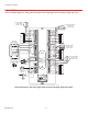
WIRING
Follow these steps for wiring all systems. However, wiring will vary depending on equipment. For conventional sys-
tems, refer to this page. For heat pump systems, see pages 6 and 7. For dual fuel systems, see pages 8 and 9.
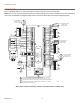
Wiring must comply with applicable codes, ordinances, and regulations. Use the following wiring diagrams to wire
the zone panel to the thermostats and dampers.
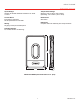
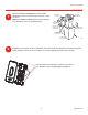
The HZ432 offers many innovations for wire management and organization: wires can be run
behind the panel, through wire channels on its sides, and attached to a wiring anchor with a
cable tie.
M24743
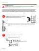
Install thermostats using instructions provided with thermostats.
Connect thermostat to zone panel. To connect wire to the panel, strip
approximately 1/4 in. of insulation and push wire into terminal. To
release wire, press the button on top of the terminal.
3
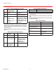
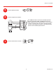
Install dampers using instructions provided with dampers.
Connect dampers to zone panel.
NOTE: Multiple dampers can be wired in parallel.
4
M24808
Rc
R
C
W
W2
Y
Y2
G
M1
M4
M6
R
C
W1/E
W2
W3
Y1
Y2
G
O/B
L
ZONE 4
DAMPER
THERMOSTAT
M24920
ARD OR ZD DAMPER SPRING-OPEN POWER-CLOSED
ZONE 3
DAMPER
M1
M4
M6
R
ZONE 1
DAMPER
RRD OR MARD DAMPER POWER-OPEN POWER-CLOSED
M4 OPEN
M6 CLOSED
M1 COMMON
ARD OR ZD DAMPER SPRING-OPEN POWER-CLOSED
ZONE 2
DAMPER
CAUTION: Voltage Hazard.
Can cause electrical shock or equipment damage. Disconnect power before beginning installation.
Wire entire panel before applying transformer power.