Installation and Operation Manual BENDIX/KING® KMA 28 FAA-Approved TSO C50c, C35d JAA-Approved JTSO-2C35d, C50c Audio Amplifier /Intercom/ Marker Beacon Receiver Document P/N 006-10565-0000 REVISION 0, SEPTEMBER 2000 WARNING Prior to export of this document, review for export license requirement is needed. Honeywell International, Inc. 2000© Copyright Notice Reproduction of this publication, or any portion thereof, by any means without the express written permission of Honeywell International, Inc.
Bendix/King KMA28 Audio Amplifier/Intercom/Marker Beacon Receiver Table of Contents 1 SECTION I GENERAL INFORMATION ......................................................................... 1-1 1.1 1.2 1.3 1.4 1.5 1.6 1.7 1.8 INTRODUCTION...........................................................................................................1-1 SCOPE .............................................................................................................................1-1 EQUIPMENT DESCRIPTION ....
Bendix/King KMA28 Audio Amplifier/Intercom/Marker Beacon Receiver 2.11.1 OPERATIONAL CHECKOUT ......................................................................................2-10 2.11.2 RECEIVER SENSITIVITY ...........................................................................................2-11 2.12 CELLULAR INTERFACE CHECKOUT ...........................................................................2-11 2.13 FINAL INSPECTION ...................................................................
Bendix/King KMA28 Audio Amplifier/Intercom/Marker Beacon Receiver Section I GENERAL INFORMATION 1.1 INTRODUCTION The KMA 28 represents the next step in cockpit audio control and intercommunications. Using proprietary IntelliVox® design, this unit eliminates the requirements for intercom squelch adjustments. The unit is designed for outstanding ergonomics and visually defined mode annunciation and selection. Before installing and/or using this product, please read this manual completely.
Bendix/King KMA28 Audio Amplifier/Intercom/Marker Beacon Receiver A six-station voice activated (VOX) intercom is included in the KMA 28. This system has the advanced IntelliVox® circuitry that eliminates manual adjustments. The system contains six separate VOX mic circuits, and only opens the microphone channel in use. The intercom system incorporates pilot isolate and crew modes, two stereo (or mono depending on unit) music inputs with "Soft Mute," and LED indicators for swap and transmit indications.
Bendix/King KMA28 Audio Amplifier/Intercom/Marker Beacon Receiver 1.5 SPECIFICATIONS TSO COMPLIANCE C35d, Class A C50c, Class A RTCA/DO-214 RTCA/DO-143 RTCA/DO-160C RTCA/DO-178B ENVIRONMENTAL Qualifications: A1D1/CA(MN)XXXXXXBBBBTBKXX Temperature Range: Operating: -15º C to +55ºC Storage: -55º C to +85ºC Altitude: Up to 50,000 feet in an non-pressurized area of the cockpit. DIMENSIONS: Height: 1.3 in. (3.3 cm) Width: 6.25 in. (16.9 cm) Depth: 6.8 in. (17.3 cm) WEIGHT (With Rack & Connectors): 1.5 lb. (0.
Bendix/King KMA28 Audio Amplifier/Intercom/Marker Beacon Receiver Intercom Positions: Music Inputs: Music Muting: Distortion: Mic Freq. Response, 3 dB: Music Freq. Response, 3 dB: Frequency: Sensitivity: Low: High: Intercom Specifications 6 places (with individual IntelliVOX® circuits) 2 (Stereo) >-30 dB "Soft Mute" when Com or intercom active.
Bendix/King KMA28 Audio Amplifier/Intercom/Marker Beacon Receiver 1.7 EQUIPMENT REQUIRED BUT NOT SUPPLIED a) b) c) d) e) f) g) h) 1.8 Circuit Breaker: 1 ea. 3 amp Speaker, 4 Ω Headphone Jacks (Stereo, as Required) Microphone Jacks (as Required) Headphones, 150 Ω (Stereo), up to 6 as required Microphones, up to 6 as required Marker Antenna (75 MHz, VSWR <1:1.5, 50 ohm, and cable (RG400 R/U) Interconnect Wiring LICENSE REQUIREMENTS None 006-10565-0000 Page 1-5 Rev. 0, Sept.
Bendix/King KMA28 Audio Amplifier/Intercom/Marker Beacon Receiver Section II - Installation 2.1 GENERAL INFORMATION 2.1.1 SCOPE This section provides detailed installation and interconnect instructions for the Honeywell, Inc. KMA28 Audio Selector Panel/Intercom System with internal Marker Beacon. Please read this manual carefully before beginning any installation to prevent damage and post-installation problems. Installation of this equipment requires special tools and knowledge. 2.1.
Bendix/King KMA28 Audio Amplifier/Intercom/Marker Beacon Receiver 2.3.3 Mounting Rack Installation Set the unit aside in a safe location until needed. Install the tray using six FHP 6-32 x ½" screws. The audio selector panel must be supported at front and rear of the mounting tray. 2.3.4 Connector Assembly The unit connectors mate directly with the circuit boards in the KMA 28. The connectors are a Molex crimp-type, and require the use of a Molex hand crimp tool, EDP P/N 11-010203, CR6115B (or equiv.).
Bendix/King KMA28 Audio Amplifier/Intercom/Marker Beacon Receiver that you use insulated washers to isolate the ground return path from the airframe to all headphone and microphone jacks. 2.4.2 Existing KMA-24 Installation If the installation replaces a KMA-24 (series –00, -01, -02 or -03), the existing 44 pin connector can be used for the bottom connector of the KMA 28 tray as is, providing it is properly installed and wired.
Bendix/King KMA28 Audio Amplifier/Intercom/Marker Beacon Receiver 2.4.7 "Swap" Mode When a momentary, normally open, push-button switch is connected between pin 10 on the top connector and aircraft ground, the user can switch between Com 1 and 2 by depressing this switch without having to turn the mic selector switch. This yoke-mounted switch eliminates the need to remove your hands from the yoke to change transceivers. 2.4.
Bendix/King KMA28 Audio Amplifier/Intercom/Marker Beacon Receiver in the entertainment devices into the system. The audio signal at the entertainment input must be a minimum of 500 mV P-P per channel for optimum music performance. All entertainment devices must be switched off for both takeoff and landing. 2.4.10.1.2 Entertainment distribution Entertainment source #1 provides music for the pilot and copilot positions, while entertainment source #2 provides music for the four passenger positions.
Bendix/King KMA28 Audio Amplifier/Intercom/Marker Beacon Receiver pilot’s PTT is activated, his voice is heard over the speaker. The copilot can continue to use the selected com. We recommend installing a toggle switch to connect the cabin speaker output (pin W, bottom connector) to a rear or public address speaker instead of the cockpit speaker close to the pilot. This will prevent feedback. 2.4.13 PA Mute (J1, Pin 18) Pin 18 of J1 is a TTL logic output that is pulled low during PTT operation.
Bendix/King KMA28 Audio Amplifier/Intercom/Marker Beacon Receiver 2.6 Adjustments The KMA 28 is factory adjusted to accommodate the typical requirements for most aircraft configurations. There are five adjustments however, that will allow the installer to tailor the specific functions. Marker Gain CW- Reduce 223 133 111 231 211 Front of Unit MKR Low Sense CW Decrease Sens.
Bendix/King KMA28 Audio Amplifier/Intercom/Marker Beacon Receiver connected to pin W of the J3 connector. On the AirCell interface diagram these are listed as data/fax lines, but they are used for voice interface in this case. Use a 2-conductor with shield cable, and connect the shield to Pin M of the J3. If interface is desired with another type of wireless telecommunications unit, the aircraft owner can purchase an after-market interface cable.
Bendix/King KMA28 Audio Amplifier/Intercom/Marker Beacon Receiver 2.
Bendix/King KMA28 Audio Amplifier/Intercom/Marker Beacon Receiver 2.10 Post Installation Checkout After wiring is complete, verify power is ONLY on pin 20 of the J1 (bottom connector), and airframe ground on bottom connector pin Z. Failure to do so will cause serious internal damage and void the warranty. 2.11 Unit Installation To install the KMA 28, gently slide the unit into the mounting rack until the hold-down screw is engaged.
Bendix/King KMA28 Audio Amplifier/Intercom/Marker Beacon Receiver 15. Verify that the audio selector panel system does not adversely affect any other aircraft system by systematically switching the unit on and off, while monitoring the other avionics and electrical equipment on the aircraft. 2.11.1.1 Marker Checkout 1. Connect a ramp generator at the antenna end of the marker coax.
Bendix/King KMA28 Audio Amplifier/Intercom/Marker Beacon Receiver Section III KMA28 OPERATION GENERAL INFORMATION KMA28 controls 3.1 Audio Selector Receiver audio is selected through two momentary and six latched, push-button, backlit switches. Com 1 and Com 2 are the momentary switches. Because the rotary microphone selector switch controls what transceiver is being heard, the Com l and Com 2 push-buttons are of the momentary type and do not remain in when selected.
Bendix/King KMA28 Audio Amplifier/Intercom/Marker Beacon Receiver 3.1.3 Public Address (PA) Function The KMA 28 has a public address capability when an optional external PA switch is installed. When this switch is put into the PA position, the pilot’s microphone is placed on a speaker output. The copilot can continue to use the selected Com radio. When this PA function is installed a separate cabin speaker (rather than the cockpit speaker) is usually utilized to prevent feedback. 3.
Bendix/King KMA28 Audio Amplifier/Intercom/Marker Beacon Receiver 3.3.1 Swap Mode (Switch from Com 1 to Com 2 remotely) With an optional yoke mounted, momentary switch, the pilot can change from the current Com transceiver to the other by depressing this switch. When “Swap Mode” is active, an annunciator in the lower right corner of the unit will illuminate, indicating that the mic selector switch position is no longer current .
Bendix/King KMA28 Audio Amplifier/Intercom/Marker Beacon Receiver headphones on the cellphone. The pilot PTT will switch the pilot mic to the COM 1, and allow continued aircraft communications as well. NOTE: Placing the mic selector switch in the TEL position will disable pilot and copilot intercom, as the intercom circuit is transferred to the telephone use. In crew or ISO mode, placing the switch in TEL mode removes the passengers access to the telephone.
Bendix/King KMA28 Audio Amplifier/Intercom/Marker Beacon Receiver path. Moving your head through a vent air stream may cause the IntelliVox® to open momentarily. This is normal. For optimum microphone performance, Honeywell recommends installation of a Microphone Muff Kit from Oregon Aero (1-800-888-6910). This will not only optimize VOX acoustic performance, but will improve the overall clarity of all your communications. 3.4.
Bendix/King KMA28 Audio Amplifier/Intercom/Marker Beacon Receiver 3.4.2.3 Entertainment Input The audio selector panel has provisions for two separate entertainment input devices. They operate independently in the KMA28. The volume control does not affect music level. While in the ISO (Isolate) mode, the copilot will hear Entertainment 1 while the four passengers will hear Entertainment #2. The pilot will hear Entertainment 1 at a level muted about 95%.
Bendix/King KMA28 Audio Amplifier/Intercom/Marker Beacon Receiver Table 3-1 Intercom Modes Mode Pilot Hears Copilot Hears Passenger Hears Telephone Comments Isolate A/C Radios Copilot and passenger intercom Passenger and Copilot intercom “Phone Booth” mode Entertainment #1 Entertainment #2 This mode allows the pilot to communicate without the others bothered by the conversations.
Bendix/King KMA28 Audio Amplifier/Intercom/Marker Beacon Receiver When the intercom is in ALL mode, the pilot can speak on the phone only if the mic selector switch is in TEL position. All intercom positions will hear the telephone conversation. Anyone who places his or her switch into the “off-hook” position will also be heard on the phone. All will hear selected audio. Com 1 audio is automatically heard in the headsets. The pilot will have transmit capability on Com 1, simply by using the PTT switch.
Bendix/King KMA28 Audio Amplifier/Intercom/Marker Beacon Receiver Appendix A – Installation Drawings 1.35 in (34.29 mm) Cutout size for front mount installation 6.32in (160.1 mm) Cutout size for rear mount installation 1.30 in (33.02 mm) 6.2 in (152.7 mm) Weight: 1.5 lb with tray and connectors ( .
Bendix/King KMA28 Audio Amplifier/Intercom/Marker Beacon Receiver 233 211 231 6.37 6.95 111 123 113 133 223 6.28 0.75 0.11 0.60 C 0.65 0.35 1.31 0.65 1.25 5.25 0.80 Figure 4-1 Tray Dimensions in inches 006-10565-0000 Appendix A Rev. 0, Sept.
Bendix/King KMA28 Audio Amplifier/Intercom/Marker Beacon Receiver 6.21 in Top View 7.48 in 5.94 in 6.28 1.35 1.25 Figure 4-2 Unit External Dimensions in inches 006-10565-0000 Appendix A Rev. 0, Sept.
Bendix/King KMA28 Audio Amplifier/Intercom/Marker Beacon Receiver Figure 4-3 Tray Assembly Drawing 006-10565-0000 Appendix A Rev. 0, Sept.
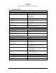
Bendix/King KMA28 Audio Amplifier/Intercom/Marker Beacon Receiver Appendix B Bottom Connector Interconnect 9 Com 1 Audio Hi Communications Transceiver #1 Com 1 Lo P R 19 L Com 1 Mic Audio Hi Com 1 Mic Key Com 1 Spr Load Com 1 Spr Load Com 1 SPR Load See Note 8 10 Com 2 Audio Hi Communications Transceiver #2 Com 2 Lo H V 16 M J Com 2 Mic Audio Hi Com 2 Mic Key Com 2 Spr Load Com 2 Spr Load Com 2 SPR Load Com 3 Audio Hi Communications Transceiver #3 Com 3 Lo K 15 Com 3 Mic Audio Hi Com 3 M
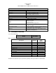
Bendix/King KMA28 Audio Amplifier/Intercom/Marker Beacon Receiver Appendix C Top Connector Interconnect J2 TOP CONNECTOR 1 2 3 B 12 11 N Pilot Phones (L) -see bottom connector. Copilot Phones (L) Copilot Phones (R) Copilot Phones Lo Pass. Phones (L) Pass. 1 PhonesJack Pass Phones (R) Pass. Phones Lo 4 D Pass. Mic Hi 5 E Pass. Mic Hi 6 F Pass. Mic Hi 7 H Pass. Mic Hi Pass. Mic Lo Pass. 1 Mic Jack Pass. Mic Lo Pass. 3 Mic Jack Pass. 3 Phones Jack Pass. 4 Mic Jack Pass. 4 Phones Jack Pass.
Appendix D- Instructions for FAA Form 337 and Continuing Airworthiness 7.1 Instructions for FAA Form 337 One method of airworthiness approval is through an FAA Form 337, Major Repair and Alteration (Airframe, Powerplant, Propeller, or Appliance) In the case of the KMA 28, you may use the following text as a guide. Installed audio selector and 6-place intercom, Honeywell KMA 28, part number 066-01176(XXXX) in ( location ) at station . Installed per AC43.
Appendix E RTCA DO160C (EUROCAE ED-14) Environmental Qualification Form Audio Selector Panel/Intercom/Marker Beacon Receiver Part Number: 7000M-S FAA TSO Number: C50c, C35d Class A, JTSO 2C35d and JTSO C50c Manufacturer: PS Engineering Incorporated 9800 Martel Road Conditions Temperature and Altitude Low Temperature High Temperature In-flight Loss of Cooling Altitude Decompression Overpressure Temperature variation Humidity Shock Operational Crash Safety Vibration Explosion Waterproofness Fluids Susceptibil