
Product Data


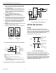


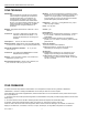
Table Of Contents

1
L404A,B PRESSURETROL® CONTROLLERS
1. Assure all wiring complies with applicable electrical
codes, ordinances and regulations. Use NEC Class 1
(line voltage) wiring.
2. For normal installation, use moisture-resistant No. 14
wire suitable for at lease 167°F (75°C) when you are
using the controller with a flame safeguard primary
control, or at least 194°F (90°C) when using it with a
programming control.
3. For high temperature installations, use
moisture-resistant No. 14 wire, selected for a
temperature rating above the maximum operating
temperature.
4. All models have a terminal block inside the cover (see
Fig. 3) and a 7/8 in. (22 mm) hole in one side for 1/2 in.
conduit, cable or wires. Remove the front cover by
loosening the screw at the bottom of the main scale.
5. Refer to Fig. 4 and 5 for typical hookups. Follow the
burner or boiler manufacturer wiring diagrams, if
provided.
6. Make sure the loads do not exceed the Switch Contact
Ratings in the Specifications section.
7. Replace the front cover when the wiring is completed.
RISE
RISE
L404A L404B
BREAKS ON
PRESSURE RISE
TO SETPOINT
MAKES ON
PRESSURE RIS
E
TO SETPOINT
M19535
Fig. 3. L404 terminal blocks and internal schematics.
L1
2
1
L2
SPST
CONTROLLER
FLAME
(HOT)
SAFEGUARD
POWER
CONTROL,
SUPPLY
MOTOR, OR
OTHER LOAD
L2
1
2
PROVIDE DISCONNECT MEANS AND OVERLOAD PROTECTION
AS REQUIRED.
HIGH LIMIT—L404A BREAKS WHEN PRESSURE RISES
TO SETPOINT.
LOW LIMIT—L404B BREAKS WHEN PRESSURE FALLS TO SETPOINT
MINUS DIFFERENTIAL.
OPERATING CONTROLLER—L404A BREAKS WHEN PRESSURE RISE
S
TO SETPOINT, AND MAKES AGAIN WHEN PRESSURE FALLS TO
SETPOINT MINUS DIFFERENTIAL.
M1953
6
Fig. 4. L404 used as a limit or as an operating controller.
LOW VOLTAGE RELAY
L404
L1
(HOT
)
L2
PROVIDE DISCONNECT MEANS AND OVERLOAD PROTECTION
AS REQUIRED.
24 VOLT
THERMOSTAT
LOAD
THERM
POWER
SUPPLY
1
2
M894
0
1
Fig. 5. L404 with a low voltage relay.
SETTING AND CHECKOUT
Setting
In all models, except the L404A1651 which has a fixed
differential, the differential is subtractive from the main scale
set point. The upper operating point is determined by the main
scale set point, while the lower operating point is determined
by the main scale setting less the differential setting.
Operating points are shown in Fig. 6.
MAIN SCALE SETPOINT
(SWITCH BREAKS)
SUBTRACTIVE
DIFFERENTIAL
L404A
PRESSURE
RISE
DIFFERENTIAL SETTIN
G
(SWITCH MAKES)
MAIN SCALE SETPOINT
(SWITCH MAKES)
SUBTRACTIVE
L404B
DIFFERENTIAL
PRESSURE
RISE
DIFFERENTIAL SETTIN
G
(SWITCH BREAKS)
M19537
Fig. 6. L404 operating points.
Adjust the main scale set point for the desired operating
pressure by turning the main scale adjusting screw (Fig. 7) on
the top of the case until the main scale setting indicator is at
the desired value. On an L404A (except the L404A1651,
which has a fixed differential) or L404B, adjust the differential
setting by turning the differential adjusting screw (Fig. 7) until
the differential setting indicator is at the desired value. The
scaleplates are marked psi and kg/cm
2
.
95C-10187B–1 6