
Specification


SWIVEL MOUNTING
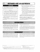
L4064A,B,E,F,J,R.T may be swivel mounted. The
swivel
br
acket requires a
1-9/16
in. [39.7
mm]
hole in
the
plenum (Fig. 3).
1. Use bracket as a template
to
make the location of
mounting
holes in plenum. Drill
or
punch holes
for
mounting screws.
2.
Fasten the bracket in place with furnished screws.
Start the screws
but
do
not tighten.
3. Insert element
tube
through bracket, straighten
controller, and fasten. Tighten the mounting screws
securely.
It may be necessary
to
rotate the bracket to
tight
en
all screws sec
ur
ely.
32612A
S
WIVEL
BRACKET
\
REQUIRE
1·9/16
in.
(40
mm]
DIAMETER
HOLE
IN PLENUM
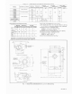
FIG.
3-SWIVEL
MOUNTING. REQUIRES A 1-9/16
in. [39. 7 mm] DIAMETER MOUNTING HOLE
FOR
ELEMENT INSERTION.
RIGID BRACKET MOUNTING
When mounting control on bracket, make sure
setscrew strikes tube frame and not inner
sens-
ing element.
L4064A,B,E,F,J,R.T may be mounted using a rigid
bracket. The rigid bracket requires a
hole 0.80 in. [20.3
mm]
diameter for mounting (Fig. 4).
1.
Use bracket as a template to mark the location of
mounting
holes in plenum. Drill
or
punch holes for
mounting screws.
2.
Fasten bracket
in
place with furnished screws.
Tighten the screws securely.
3.
Insert element tube through bracket, straighten
controller and fasten by tightening setscrew. Be sure
screw strikes tube frame and does not strike inner
sensing element.
4.
For replacement installations with existing 1 in.
[25.4
mm]
diameter hole. SUPER TRAOELINE and
TRADELINE models are suppli
ed
with split steel
bushings and wire snap ring.
Follow the instructions
below for using the
steel bushing adapter.
5
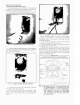
STEEL BUSHING ADAPTER
(SUPER TRADELINE and TRADELINE models)
1.
Insert one-half of the split steel bushing through the
wire ring (Fig.
5). It may be necessary to spread the ring
slightly.
2. Insert the other half
of
the steel bushing into the
ring making sure tabs and ears are at the same ends.
3. Place bushing assembly on element, ear end first.
4. Holding bushing at seams, push firmly
to
the
control end
of
element.
5. Insert element tube with adapter through bracket,
straighten
controller and fasten. Tighten setscrew. Be
sure screw strikes bushing and not inner sensing
element.
~FURNACE
PLENUM
FIG.
4-RIGID
BRACKET MOUNTING REQUIRES A
HOLE 0.80 in. [20.3 mm] DIAMETER FOR
MOUNTING.
L4064
HELICAL ELEMENT
2196A
FIG. 5- USING TRADELINE ADAPTER.
WIRING
Disconnect power supply before beginning installa-
tion
to
prevent electrical shock and eq
uipm
ent
dama
ge
.
All wiring must comply with local
el
ectrical codes
and ordinances or in the absence of
local codes with
the National
Electrical Code ANSI
C1
-
1981-NFPA
70.
Follow
burner
or furnace manufacturer's instructions
if
available; otherwise, proceed
as
follows.
--
~~~~~
-IMPORTANT~
~~~~
~...,
The metal-fib
erboard
jumper
must
be
removed
when the
limit is used in the low voltage circuit. To
remove,
pull out. To replace, push metal
fiberboard
jumper
in with tab side up.
60-2258-2