
Submittal Sheet

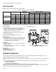

Table Of Contents

L4079A,B,W PRESSURETROL
®
LIMIT CONTROL
3 60-2156—03
INSTALLATION
When Installing This Product…
1. Read these instructions carefully. Failure to follow them
could damage the product or cause a hazardous
condition.
2. Check on the ratings given in the instructions and
marked on the product to make sure the product is
suitable for your application.
3. Installer must be a trained, experienced service
technician.
4. After installation is complete, check out the product oper-
ation as provided in these instructions.
Location
PressureTrol
®
Limit Controllers must be mounted above the
water line in steam boilers. They can be mounted alongside
the pressure gauge, at a remote location, in a fitting provided
by the boiler manufacturer, or in special mountings on
low-water cutoffs.
Mounting
See Fig. 1 for mounting dimensions.
A steam trap must always be connected between the
PressureTrol
®
unit and the boiler. The steam trap prevents
boiler scale and corrosive vapors from attacking the
diaphragm.
Pressure Gauge Mounting:
To mount the limit control beside a pressure gauge, remove the
gauge and install in its place a steam trap with a tee on top.
Mount the PressureTrol
®
unit and pressure gauge on the side
of the tee by means of nipples and elbows.
Remote Mounting:
If excessive vibration seems likely to affect the operation of the
control, it may be located remotely, as long as all piping is
suitable and properly pitched to drain all condensation back to
the boiler.
Boiler Mounting:
If it is not convenient to mount the control adjacent to the
pressure gauge, install a steam trap at a location on the boiler
recommended by the boiler manufacturer and screw the unit
directly to the steam trap.
WIRING
WARNING
Electrical Shock Hazard.
Can cause severe injury, death or property damage.
Disconnect the power supply before beginning wiring.
More than one power supply disconnect may be
required.
All wiring must comply with local codes and ordinances. See
Fig. 2 for internal schematics and wiring.
Fig. 2. Schematics and wiring. L4079A breaks both sides
of power supply; L4079B,W breaks hot side only.
Setting
To set the control, turn the pressure adjusting screw (see Fig.
3) until the pressure setting indicator on the front of the case is
in line with the required control pressure setpoint. The indicator
setting is the point at which the switch breaks contact.
Fig. 3. Controls and indicators on L4079A. L4079B,W is the
same except for having only one reset button.
M22436
LINE VOLTAGE
THERMOSTAT
L4079A
L4079B, W
L1 (HOT)
L2
POWER
SUPPLY
TO
THERMOSTAT
(HOT)
TO POWER
SUPPLY
MOTOR
TO
MOTOR
RISE
RISE
RISE
1
PROVIDE DISCONNECT MEANS AND OVERLOAD
P
ROTE
CTION
AS REQUIRED.
1
M22437
PRESSURE
ADJUSTING
SCREW
PRESSURE
SETTING
INDICATOR
SCALEPLATE
MANUAL
RESET
BUTTONS