® Dolphin 7850 Mobile Computer With Windows Mobile® 5.
Disclaimer Honeywell International Inc. (“HII”) reserves the right to make changes in specifications and other information contained in this document without prior notice, and the reader should in all cases consult HII to determine whether any such changes have been made. The information in this publication does not represent a commitment on the part of HII.
Table of Contents Chapter 1 - Agency Information Label Locations ....................................................................................................................1-1 Regulatory and Safety Approvals for all Dolphin Terminals ................................................1-3 Chapter 2 - Getting Started Out of the Box ......................................................................................................................2-1 Today Screen.......................................
Chapter 5 - Using the Imager Scanner Engine Overview.............................................................................................................................. 5-1 Available Engines ................................................................................................................ 5-1 Available Laser Engines ...................................................................................................... 5-2 Laser Specifications ..........................................
Menu Options ...................................................................................................................... 8-9 Discovered Devices........................................................................................................... 8-10 Refreshing Discovered Devices................................................................................... 8-10 Making the Terminal Discoverable .............................................................................. 8-10 Pairing ..
Chapter 13 - Customer Support and Warranty Technical Assistance......................................................................................................... 13-1 Online Technical Assistance........................................................................................ 13-1 Product Service and Repair............................................................................................... 13-1 Online Product Service and Repair Assistance .............................................
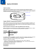
1 Agency Information Label Locations Dolphin 7850 mobile computers meet or exceed the requirements of all applicable standards organizations for safe operation. However, as with any electrical equipment, the best way to ensure safe operation is to operate them according to the agency guidelines that follow. Please read these guidelines carefully before using your Dolphin mobile computer. Compliance Label Laser Safety Label Dolphin 7850 802.
Honeywell shall not be liable for use of our product with equipment (i.e., power supplies, personal computers, etc.) that is not CE marked and does not comply with the Low Voltage Directive.
Die maximale Ausgangsleistung für die IR LED ist 145,1 uW. LED's werden bei einer Frequenz von 115,200 Hz mit einem Auslastungsgrad von 18,75% gepulst, wobei die Einschaltdauer eines einzelnen Impulses 1.6275 x 10⁻⁶ Sekunden beträgt. Regulatory and Safety Approvals for all Dolphin Terminals Parameter Specification U.S.A.
RF, Regulatory, and Safety Agency Approvals—802.11b/g (WLAN) and/or Bluetooth Parameter Specification U.S.A. FCC Part 15.247 Canada RSS 210 Canadian Compliance This Class B digital apparatus complies with Canadian ICES-003. Operation is subject to the following two conditions: (1) this device may not cause harmful interference, and (2) this device must accept any interference received, including interference that may cause undesired operation.
Microwaves The radio in the Dolphin RF terminal operates on the same frequency band as a microwave oven. Therefore, if you use a microwave within range of the Dolphin RF terminal you may notice performance degradation in your wireless network. However, both your microwave and your wireless network will continue to function. The Dolphin Batch terminal does not contain a radio, and therefore, is not affected by microwave ovens.
1-6
2 Getting Started Out of the Box When you open the carton, please verify that the carton contains the following items: • Dolphin 7850 mobile computer (the terminal) • Main battery pack (7.4v, li-ion) • Getting Started CD-ROM • Dolphin 7850 Mobile Computer Quick Start Guide Be sure to keep the original packaging in the event that the Dolphin terminal should need to be returned for service. For details, see Limited Warranty on page 13-2.
Today Screen Initial boot and system resets end on the Today screen; see Resetting the Terminal on page 3-15. Tap to access the Start menu Tap to adjust the volume Tap to change the date and time These are icons of programs running in the background. Tap to open the program or access a menu for it. Note: You can also open the Today screen at any time by tapping Start > Today.
Using the Stylus Use the stylus or your finger to select or enter information on the touch panel. The stylus functions as a mouse; generally, a tap is the same as a click. Tap Tap the touch panel once to open menu items and select options. Drag Hold the stylus on the screen and drag across the screen to select text and images. Tap & hold Tap and hold the stylus on an item and a pop-up menu appears. On the pop-up menu, tap the action of the task you want to perform.
2-4
3 Hardware Overview There are a number of standard configurations as well as charging and communication peripherals and accessories to maximize the efficiency of your application setting. Standard Terminal Configuration • • • • • • • • Windows Mobile 5.0 PXA270 520MHz processor 64MB volatile system memory for running programs & 64MB non-volatile Flash memory for storing data 24-key calculator-style numeric with scrolling alpha or 38-key calculator-style numeric with full alpha 3.5 in.
Peripherals The following items are sold separately and enhance the capabilities of your Dolphin terminal. Dolphin HomeBase™ Device This charging and communication cradle supports both RS-232 and USB communication, enabling your terminal to interface with the majority of PC-based enterprise systems. When a terminal is seated in the HomeBase device, its main battery pack charges in less than four(4) hours. For more information, see Dolphin HomeBase Device on page 9-1.
Accessories The following items are sold separately and enhance the capabilities of your Dolphin terminal. Battery Door Tether For more information, see Battery Door Tether (Optional) on page 3-7. Holster The holster holds one terminal around the waist. Li-ion Battery Pack These are 7.4Vdc, 14.1 watt hour Li-on replacement battery packs; see Battery Power on page 3-11. Protective Cover The protective cover wraps around the terminal to protect it from wear and tear.
Front Panel Features 3.5 inch 1/4 VGA Touch Panel Display Decode LED Scan LED Keyboard Protection Ribs Decode and Scan LEDs The Scan LED lights red when you press the Scan trigger in scanning applications. The Decode LED lights green when a scanned bar code is successfully decoded. For more information, see LEDs on page 4-1. Keyboard Protection Ribs These ribs protect the keyboard and prevent keys from being pressed accidentally when the terminal is placed facedown on a flat surface.
Back Panel Features Battery Door DC Power Jack Tether Holes Battery Door The battery door covers and secures the main battery pack in the battery well. There is a mechanical switch on the terminal under this door that puts the terminal in suspend mode (see page 3-15) while the battery door is open. This door must be closed for the terminal to resume operation. For more information, see Installing the Main Battery Pack on page 3-11. DC Power Jack Located on the bottom of the pistol-grip handle, the 9.
Side Panel Features Beeper IrDA Port Angled Display Scan Engine Window I/O Connector Scan Trigger Integrated Pistol-Grip Handle Stylus Loop Stylus Slot Tether/Lanyard Attachment Point Note: This graphic shows the right side of the Dolphin 7850 terminal. Angled Display The touch panel display (see page 3-4) tilts up toward the user, which improves application viewing when operating the terminal and reduces glare.
IrDA Port The infrared port is IrDA-enabled (Infrared Data Association) and communicates with other IrDA-enabled devices such as PCs, printers, modems, or other Dolphin 7850 terminals. The maximum data transfer speed is 115 Kbps with a duty cycle of 18.75%. For more information, see Using Infrared Communication on page 7-8. Scan Trigger The front of the pistol-grip handle contains a scan trigger that activates the scan engine. The scan trigger also wakes the terminal from Suspend Mode (see page 3-15).
4. Remove the battery door. 5. Take the clip piece, loop the lanyard through the tether holes on the battery door as shown below. 6. Reattach the battery door. 7. Snap the leather strap into the clip.
I/O Connector I/O Connector This I/O connector has 17 pins that are designed to work exclusively with Dolphin 7850 peripherals and cables. This connector • Powers the terminal. • Charges the main battery. • Supports communication with a host workstation via Microsoft ActiveSync (see page 7-3). • Supports RS-232 (up to 115 Kbps) and USB (up to 12 Mbps) communication.
Rubber Bumpers There are two sets of rubber bumpers: one set below the scan engine window and the other set on the bottom front of the pistol-grip handle. Rubber bumpers enable you to set the terminal down on a flat surface with easy access to the handle, so you can pick up and put down the terminal with ease. Front Rubber Bumpers Pistol-Grip Rubber Bumpers Front Rubber Bumpers The front rubber bumpers enable you to rest the terminal on a flat surface without damaging the scan engine window.
Battery Power The intelligent battery technology built into the terminal features two types of battery power: • The main battery pack installed under the battery door on the back panel. • The backup battery located inside the terminal. Both batteries work together to prevent data loss when the terminal is used over long periods of time. Main Battery Pack ! We recommend use of Honeywell Li-Ion battery packs. Use of any non-Honeywell battery may result in damage not covered by the warranty.
Charging Options When the battery is installed in the terminal, you can insert the terminal into any one of the following peripherals to charge the main battery pack: • Dolphin HomeBase Device (see page 9-1) • Dolphin ChargeBase Device (see page 11-1) • One of the charging cables (see page 12-1) To fully charge the li-ion battery outside the terminal, use one of the following: • Dolphin QuadCharger Device (see page 10-1) • Auxiliary Battery Well of the Dolphin HomeBase device Charge Time A completely discha
Default Critical and Low Battery Points Dolphin terminals are programmed to display warnings when the battery reaches critical and low battery points. The following registry entry sets both warning points: [HKEY_LOCAL_MACHINE\System\CurrentControlSet\Control\Power] There are two DWORD values in this registry entry: LowBatt and CriticalBatt. The default values for these entries are as follows: LowBatt=19 (25%) This sets the Low Battery point to 25% (19 hex=25 decimal).
Checking Battery Power Tap Start > Settings > System tab > Power. For more information, see Power on page 6-12. Storage Guidelines To maintain optimal battery performance, follow these storage guidelines: • Avoid storing batteries outside the specified range of -4° to 104° F (-20° to 40°C) or in extremely high humidity. • For prolonged storage, do not keep batteries stored in a charger that is connected to a power source.
Resetting the Terminal There are two ways to reset the Dolphin terminal: a soft reset and a hard reset. Soft Reset (Warm Boot) A soft reset re-boots the device without losing RAM data. You would perform a soft reset 1) when the terminal fails to respond, 2) after installing software applications that require a reboot, or 3) after making changes to certain system settings. 1. Press and hold the Red + ESC keys for approximately five seconds.
Troubleshooting If the terminal does not wake when you press the scan trigger, • The battery door may not be fully closed. The mechanical switch under the battery door prevents the terminal from resuming operation until the door is closed. • The main battery might be too low to resume operation. Remove the battery and install a fully charged battery or connect the terminal to a Dolphin charging peripheral.
Terminal Technical Specifications Basic Features Form Factor: Purpose-built, compact, handle-style mobile computer Operating System: Windows Mobile 5.0 Development Environment: Honeywell Dolphin SDK for Visual Studio (supports C/C++, C#, and Visual Basic) Third Party Software: • SOTI MobiControl (remote device management) • PowerNet™ Terminal Emulation (TNVT, 3270, 5250) • ITScriptNet™ CPU: Intel PXA 270 312 MHz or 520 MHz Memory (RAM/ROM): 64MB/64MB and 128MB/128 MB options Display: 3.5 in.
Power Battery: Main: Lithium-ion 7.4V, 14.8 Watt-hour, hot-swappable battery pack Backup: Internal 3.6V nickel metal hydride (NiMH) battery saves RAM data for 30minutes during main battery change Run Time (estimated): WLAN: 10+ hours at 1 scan/6 sec, 1 data package logged every scan, 802.11b/g continuous connection, & display backlight on full Stand-by Time: Device suspend mode: 8 days minimum Charging: 9.
4 Using the Keyboards Overview The keyboard buttons are recessed under the overlay for maximum durability. The keyboard panel is backlit for maximum viewability in various lighting conditions. There are two keyboard options: 24-Key Keyboard (see page 4-4) 38-Key Keyboard (see page 4-7) VOL+ VOL+ DEL DEL INS ESC BKSP ALPHA F1 F2 7 \/_ 8 F4 F5 4 F7 F8 1 TUV PQRS F10 – : 2 9 6 MNO 5 JKL GHI A F ALPH F9 4 START K 1 3 WXYZ “ 0 P U F1 +[ ] .
Using the Function Keys Function keys perform specific functions and usually have the name of the function they perform. Name Key Function Backlight Toggles the keyboard backlight on and off. Backspace (BKSP) To backspace, press Red + left arrow. Backspace moves the cursor back one space and deletes each time the key combination is pressed. If you are typing text, a character is deleted each time you backspace. Backtab (BKTAB) To backtab, press the Blue + TAB.
Using the Navigation Keys Located in the center of each keyboard for easy access with either hand, the navigation keys enable you to navigate the cursor through an application screen. Press To … Move the cursor up one row or line. Move the cursor down one row or line. Move the cursor one character to the right. Move the cursor one character to the left. The navigation keys perform additional system functions when pressed in combination with the Blue and Red modifier keys.
24-Key Keyboard Navigation keys Escape Shift LED LED key key OK key Tab key VOL+ DEL INS ESC PG BKSP - SFT Alpha Lock F1 7 \/_ 4 F5 START F7 1 F8 TUV PQRS = 2 F10 – : 6 MNO 5 JKL 9 DEF ABC GHI Power F3 8 F6 F4 Backlight key F2 BKTAB TAB VOL ALPHA Modifier keys SP F9 3 WXYZ “ 0 +[ ] Toggling Between Alpha and Numeric Modes The 24-key keyboard defaults to numeric mode. Numeric mode is when you type numbers with the number keys.
24-Key Keyboard Numeric Key Combinations Key Blue Mode Num Mode Num Shift ESC Delete ESC ESC SFT *Toggle Upper/Lower/Shift *Toggle Upper/Lower/Shift *Toggle Upper/Lower/Shift Blue ***Toggle Num/Alpha Blue Mode ***Toggle Num/Alpha Red Red Mode; see 24-Key Keyboard Alpha Key Combinations on page 4-6.
24-Key Keyboard Alpha Key Combinations Key Red Mode Alpha Base Alpha Shift Alpha Caplock Alpha Shift Caplock ESC ESC ESC ESC ESC ESC SFT *Toggle Upper/ Lower/Shift *Toggle Upper/ Lower/Shift *Toggle Upper/ Lower/Shift *Toggle Upper/ Lower/Shift *Toggle Upper/Lower/ Shift Blue ***Toggle Num/ Alpha ***Toggle Num/ Alpha ***Toggle Num/ Alpha ***Toggle Num/Alpha Red Red Mode Red Mode Red Mode Red Mode Asterisk # * * * * Light Keyboard Light Keyboard Light Keyboard Light Keyb
38-Key Keyboard Navigation keys Escape Shift LED LED key key OK key Tab key VOL+ DEL INS ESC PG BKSP - SFT A Modifier keys F 4 Alpha Lock ALPH K 1 Power Backlight key P U F1 . *F2 V B G L Q W 8 5 2 0 @ F3 C H M BKTAB TAB VOL 7 START SP 9 6 D I N 3 R , X# F4 S Y E + \ / ALT J O T Z F10 F9 Alpha indicators F8 F7 CTRL F6 F5 Toggling Between Numeric and Alpha Modes The 38-key keyboard defaults to numeric mode.
38-Key Keyboard Alpha Key Combinations Key Blue Mode Alpha Base Alpha Shift Alpha Caplock Alpha Shift Caplock ESC Delete ESC ESC ESC ESC SFT *Toggle Upper/ Lower/Shift *Toggle Upper/ Lower/Shift *Toggle Upper/ Lower/Shift *Toggle Upper/ Lower/Shift *Toggle Upper/Lower/ Shift Blue Blue Mode Blue Mode Blue Mode Blue Mode Red Red Mode Red Mode Red Mode Red Mode ALPH Start Num Mode Num Mode Num Mode Num Mode Light Suspend Keyboard Light Keyboard Light Keyboard Light Keyboa
38-Key Keyboard Alpha Key Combinations Key Blue Mode Alpha Base Alpha Shift Alpha Caplock Alpha Shift Caplock \ n N N n / s S S s F1 u U U u F2 * v V V v F3 @ w W W w F4 # x X X x F5 y Y Y y F6 z Z Z z F7 t T T t F8 o O O o F9 j J J j F10 e E E e *Toggle Upper/Lower only on a double-tap. **Single-tap of SFT key changes shift mode for just the next character. Double-tap of SFT key toggles Caplock.
38-Key Keyboard Numeric Key Combinations Key Blue Mode Num Mode Num Shift ESC Delete ESC ESC SFT *Toggle Upper/Lower/Shift *Toggle Upper/Lower/Shift *Toggle Upper/Lower/Shift Blue Blue Mode Blue Mode Red Red Mode Red Mode ALPH Start Alpha Mode Alpha Mode Light Suspend Keyboard Light Keyboard Light Left Left Left Up Volume up Up Up Down Volume down Down Down Right Insert Right Right OK OK OK OK Tab Backtab Tab Tab Period .
38-Key Keyboard Numeric Key Combinations Key Blue Mode Num Mode Num Shift \ \ } / / { F1 F1 F1 F2 * F2 F2 F3 @ F3 F3 F4 # F4 F4 F5 F5 F5 F6 F6 F6 F7 F7 F7 F8 F8 F8 F9 F9 F9 F10 F19 F10 *Toggle Upper/Lower only on a double-tap.
4 - 12
5 Using the Imager Scanner Engine Overview The compact imager scanner engine uses Adaptus® Imaging Technology 5.0, which instantly reads all popular 1D and 2D bar codes and supports omni-directional aiming and decoding. This engine can also capture digital images, such as signatures and pictures of damaged inventory. Available Engines 5100 Standard Range (5100SR) 5300 Standard Range (5300SR) 8.3 mil Linear Working Range: (.020 cm) 10 mil PDF417 (.025 cm) 13 mil UPC 15 mil Data Matrix (.033 cm) (.
Available Laser Engines High Performance (HP) 5 mil 55 mil reflective Near 2.75 in (0.07 m) 5 in (0.13 m) Far 7 in (0.17 m) 66 in (1.7 m) 10 mil 100 mil reflective Near 11 in (0.28 m) 60 in (1.5 m) Far 24 in (0.6 m) 240 in (6.1 m) Working Range: Long Range (LR) Working Range: Advanced Long Range (ALR) 13 mil 100 mil reflective Near 19 in (0.48 m) 125 in (3.2 m) Far 39 in (1 m) 360 in (9.
Supported Bar Code Symbologies Symbology Type Symbology Name 1D Symbologies Codabar Code 3 of 9 Code 11 Code 32 Pharmaceutical (PARAF) Code 93 Code 128 EAN with Add-On EAN with Extended Coupon Code EAN-8 EAN-13 GS1-128 GS1 Databar Interleaved 2 or 5 2D Symbologies Aztec Codablock Code 16K Code 49 Composite Data Matrix GS1 Databar MaxiCode Micro PDF OCR PDF417 QR Code Composite Codes Aztec Mesa Codablock F EAN·UCC GS1 Databar-14 OCR OCR US Money Font MICR (E 13 B) and SEMI Font OCR-A OCR-B Postal C
Activating the Engine The scan trigger on the front of the integrated pistol-grip handle that activates the scan engine. Scan Trigger Using Demos Demos are software utilities loaded on all Dolphin terminals that demonstrate the advanced features of the terminal. Two Demos feature the scan engine: Image Demo and Scan Demo. To access these demos, tap Start > Demos, • Select Image Demo to verify imaging, or • Select Scan Demo to verify decoding.
Decoding The Dolphin terminal supports two types of image decoding: full-area imaging and Advanced Linear Decoding (ALD). Full-area Imaging Full-area imaging means that the Dolphin terminal support omni-directional aiming, which means that a positive read can be obtained from many positions. For details, see OmniDirectional Scanning Positions on page 5-4. ALD ALD provides fast reading of linear (1D) and stacked linear bar codes (e.g., PDF417).
Omni-Directional Scanning Dolphin terminals support omni-directional scanning. In general, the aiming pattern or beam is smaller when the terminal is held closer to the bar code and larger when farther from the bar code. Symbologies with smaller bars or elements (mil size) should be read closer to the terminal whereas larger bars or elements (mil size) should be read farther from the terminal. Note: To achieve the best read, the aiming beam should be centered horizontally across the bar code.
Capturing Images The image-capture process is an intuitive, split-second operation for experienced users. By following basic guidelines, however, new users can easily develop their own technique and, with practice, quickly learn to adapt to different application environments. Image Preview When the imaging process is initiated, the screen displays a preview of the object. This is a live video image of what the imager is currently viewing and has a slightly degraded appearance compared to the captured image.
5-8
6 System Settings Overview Customizable settings are available from the Start menu. Tap Start > Settings and the Settings screen opens displaying the Personal tab. Settings consists of three tabs: Personal, System, and Connections. Personal Tab System Tab Connections Tab Tab Description Personal The Personal tab provides access to personal configuration programs. For details, see Personal Settings on page 6-2.
Personal Settings To access the Personal tab, go to Start > Settings. The screen opens displaying the Personal tab. Icon Description See Page Buttons Programs hardware buttons to launch applications or execute commands. 6-3 Input Customizes the SIP. For details. 6-4 Lock Provides password protection for certain programs on the terminal. N/A Menus Customizes what appears on the Start and New menus. 6-5 Owner Information Stores your contact information.
Buttons The Buttons setting programs keyboard buttons to launch applications or execute commands. The default button assignments that appear on the Buttons window are inactive until you enable the HotKeys Power Tool. You must enable the HotKeys Power Tool to activate the button assignments in the Buttons setting. 1. Tap Start > Power Tools. 2. Tap the HotKeys icon once . 3. HotKeys is enabled and the button assignments in the Buttons setting are active. 4.
Commands The Assign a program list also contains the following commands: Command Description Opens the soft input panel. Nothing happens when the button is pressed. Performs the same function as tapping OK on the screen. Scrolls down in the open application. Scrolls left in the open application. Scrolls right in the open application. Scrolls up in the open application. Opens the Start menu.
Menus - Modifying the Start Menu You can add existing programs you use often, such as File Explorer, to the Start menu for faster access. You are not installing the program, just enabling the user to access the program from the Start menu. You can add a program to the Start Menu three ways: directly by using the Menus setting, or creating and pasting shortcuts in File Explorer on the terminal or the workstation (and using ActiveSync to transfer to the shortcut to the terminal).
3. Navigate to the Windows folder and open the Start Menu folder (My Device > Windows > Start Menu), tap and hold a blank area of the window, and tap Paste Shortcut on the pop-up menu. 4. The shortcut is now in the folder. 5. Tap the Start menu to verify that the program now appears on it.
System Settings The System tab enables you to verify and sometimes alter system parameters. To access the System tab, go to Start > Settings > System tab.
Backlight The backlight for the color display is user-defined. Tap Start > Settings > System tab > Backlight.There are two tabs: Battery and External; the options on each tab are the same. The Battery tab determines display backlight settings when the terminal is running on battery power. The External tab determines display backlight settings when the terminal is powered by an external source, such as a charge cable.
Certificates Certificates shows you the network certificates recognized by the operating system. There are personal and root certificates; each has its own tab. It is important to verify that the operating system acknowledges your certificate. If the certificate does not appear on one of these tabs, the operating system does see it, and it will not function properly during the network authentication process. For more information, see Certificates on page 8-12.
Memory Dolphin terminals have two types of memory: volatile and non-volatile. Each type of memory has its own options. Volatile Data stored in volatile memory does not persist through cold boots; see Hard Reset (Cold Boot) on page 3-15. Volatile memory is used for running and storing programs as well as storing program data and is also known as RAM memory. The Dolphin 7850 terminal can have 64MB or 128MB of volatile memory depending on your configuration.
Field Description In use Displays the total MB of that allocated memory being used in Storage and Program memory functions. Free Displays the total MB of memory available for Storage and Programs use. Storage Card Tab This tab displays the current capacity and usage statistics of the selected memory type: IPSM or Storage Card. Select the memory type from the drop-down list. IPSM is selected by default. Field Description Total storage card… The total MB of memory capacity of the selected memory.
! Anytime you stop a running program, it frees up volatile memory. Be advised that, when you stop a program here, any unsaved data in that program is lost. To free up memory without risking data loss, return to the running program, save your data, and close the application. Find Link Find searches for large files using storage memory. Clicking Find opens the Search program with Larger than 64KB already selected in the Type field. Enter the search criteria and tap Search.
Regional Settings Regional Settings enables you to customize the appearance and formatting to your geographic region. Specifically, you can customize numbers (i.e., number of decimal places allowed), currency (i.e.,using the $ or € € symbol), time, and date. These specifications apply to all screens, including the Today screen. The Region tab displays an overview of the region selected in the drop-down list at the top. The terminal is loaded with a number of pre-programmed regional settings.
Remove Programs The Remove Programs settings enables you to remove programs installed on the terminal. Use this setting to troubleshoot when you receive messages that the device is out of memory. The programs removed in the Remove Programs setting are removed from volatile memory. 1. Tap Remove Programs. In the list, select the program you want to remove. 2. Tap Remove. The following message appears: 3. Tap Yes. Wait while the program is removed. 4.
Screen Note: By default, dynamic screen rotation (i.e., the ability to switch between landscape and portrait orientation) is disabled on Dolphin 7850 terminals. Alignment Tab Tap Align Screen to re-align the screen. Remember, you first align the screen at bootup. You would need to re-align the screen again if tapping buttons or icons with the stylus no longer seems to work appropriately. ClearType Tab Dolphin terminals support ClearType font rendering.
This is the default font size setting. To change the font size, move the slider toward Smallest or Largest. The Example text changes to reflect the font change. Tap OK to save the new font size setting.
7 Communication Communication Options Dolphin terminals offer a number of communication options including Microsoft ActiveSync, infrared, and wireless radios. I/O Connector The industrial-grade, 17-pin, mechanical connector on the bottom panel (see I/O Connector on page 3-9) connects the terminal to a series of Dolphin peripherals that connect to a host workstation via USB (1.1 or higher).
Default COM Port Assignments The Dolphin terminal ships with the COM ports assigned as follows: COM Port Assignment 1 Serial port; this is the I/O connector on the bottom panel. See I/O Connector on page 3-9. 2 Bluetooth Module If there is no Bluetooth hardware installed on the terminal, this com port is unassigned. 3 Raw Infrared 4 Unassigned 5 USB virtual serial port 6 IrDA, if IrDA is enabled. If IrDA is disabled, this com port becomes available.
Using ActiveSync ActiveSync communication happens through the I/O connector on the bottom panel (see I/O Connector on page 3-9) when the terminal is connected to a Dolphin communication peripheral such as the Dolphin HomeBase device or a charge/communication cable. Hardware Requirements • Dolphin communication peripheral or cable: USB or RS-232 • Power Adapter Cable from Honeywell Software Requirements To synchronize, ActiveSync 4.
Setting Up the Terminal ! When communicating via ActiveSync, your terminal is designed to be connected to the host workstation with a Honeywell communication peripheral. We recommend use of Honeywell peripherals, power cables, and power adapters. Use of any non-Honeywell peripherals, cables, or power adapters may cause damage not covered by the warranty. You need to connect the Dolphin peripheral to the host workstation, then connect the Dolphin terminal to the peripheral.
1. Download the program to the workstation from either the Internet or the installation CD. You may see a single *.exe or setup.exe file, a *.cab file, or *.dll. (There may also be several versions of files for different device types and processors.) 2. Read any installation instructions provided by the program, such as Read Me files or other documentation. Many programs provide special installation instructions. 3. Connect the terminal to the workstation via Dolphin communication peripheral. 4.
Connections Tab The Connections Tab of Windows Mobile Settings provides access to the configuration settings for many of the terminal’s communication options. Tap Start > Settings > Connections tab. Note: The programs that appear on the Connections tab depend on the terminal’s radio configuration. Program Description See Page Beam Controls infrared communication. 7-8 Connections Accesses the connections manager to set up modem connections. 7-10 Network Cards Opens the network adapters tool.
Connecting the Terminal to a Wireless Network Establishing the terminal on a wireless network depends heavily on your network infrastructure. You will need specific information from your network administrator. Whatever your network specifics, some general steps apply: 1. The on-board radio drivers must be enabled for the terminal to transmit a signal. Verify the radio’s status in the Radio Manager (see page 7-13). 2. Enter the appropriate configuration settings for each radio installed.
Using Infrared Communication The IrDA port sends and receives data between the terminal and other devices equipped with infrared. The maximum data transfer speed is 115 Kbps with a duty cycle of 18.75%. IrDA Port Location IrDA Port Verify Beam Settings By default, the IrDA port is enabled after each hard reset. This means that the IrDA port is ready to send and receive data via infrared. Tap Start > Settings > Connections tab > Beam.
3. Tap and hold the item and select Beam File. 4. The information begins transmitting to the other infrared device. Receiving Data 1. Verify that the terminal is set to receive all incoming beams; see Verify Beam Settings on page 7-8. 2. Align the IrDA ports. 3. Have the owner of the other device send the information to you via infrared. 4. Your terminal automatically begins receiving it.
Connections Manager The connections manager sets up various network connections to Internet Service Providers (ISPs) via an external modem. If you are using one of the on-board wireless radios to connect to a network, do not enter network parameters in the connections manager. The Dolphin terminal uses the radio’s settings to connect to the network. Note: All server-assigned IP addresses use Dynamic Host Configuration Protocol (DHCP).
Proxy Server Connections If you are connected to your ISP or private network during synchronization, the terminal should download the proper proxy settings during synchronization with the workstation. If these settings are not on your workstation or need to be changed, ask your ISP or network administrator for the proxy sever name, server type, port, type of Socks protocol used, and your user name and password.
Network Cards The Connections tab (see Connections Tab on page 7-6) contains a Network Cards icon displays the network cards installed in the terminal. 1. Tap Start > Settings > Connections > Network Cards that 2. Tap on an adapter in the list to review its settings. (Server-assigned IP addresses use DHCP.) 3. If you make a change on one of these tabs, tap OK to confirm the changes. 4. You must perform a soft reset to update the registry entries; see Soft Reset (Warm Boot) on page 315.
Radio Manager The Radio Manager enables and disables the radio drivers installed in the terminal. When a radio is enabled, the radio is transmitting a signal. When disabled, the radio is not transmitting a signal. At least one radio must be enabled before you can set the terminal up on a wireless network. After the radio is enabled, you can enter the appropriate network parameters for your network. If the radio is disabled, the terminal doesn’t connect.
Radio Manager Window Field Description Radio Modes Displays the radio hardware modules currently installed on the terminal. Status Field Provides feedback on the state of the radio. The Status field reads “Ready” when the selected radio is enabled and the Radio Manager is ready to receive a command. Otherwise, the Status field displays the following messages when enabling a radio: • Success=The radio or radio combination has been successfully enabled.
USB to PC The USB to PC applet enables you to switch between RNDIS (Remote Network Driver Interface Specification) USB and Serial USB communication. Dolphin 7850 terminals default to Serial USB. Honeywell recommends using Serial USB. To change this setting, tap Start > Settings > Connections tab > USB to PC is not selected, which indicates Serial USB. . The enable option To switch to RNDIS USB, select Enable advanced network functionality and tap OK to save. (Wait as the terminal makes the change.
7 - 16
8 Wireless PAN Communication with Bluetooth Bluetooth Radio The on-board Bluetooth radio is enabled by default at startup and operates within the 2.4 GHz–2.48 GHz band. Bluetooth transmissions hop between 79 separate frequencies 1,600 times every second, and with a communication range of about 10 meters (class II). Enabling the Bluetooth Radio The Bluetooth radio must be enabled in order to connect to other devices.
Accessing BTExplorer When the Bluetooth radio is enabled, the Bluetooth icon on the Today screen appears as follows Tapping this icon once opens BTExplorer to the Favorites window. . Note: When the Bluetooth radio is disabled, tapping this icon opens a warning message, which states that the radio is not enabled and to go to the Radio Manager as described in Accessing BTExplorer on page 8-2.
Using BTExplorer BTExplorer has a New Connection Wizard for each type of Bluetooth connection you want to make; see Connection Types on page 8-7. You open BTExplorer, select the connection type, BTExplorer scans for matching devices and services, and the connection wizard walks you through the connection process. Different connection types will require different information. Make sure you have all the necessary information (PIN numbers, passkeys, MAC addresses, etc.) from the devices you want to connect to.
4. Click Next and BTExplorer scans for other Bluetooth devices in range and displays the search results. 5. Select a device and click Next. BTExplorer attempts to connect to the selected device and explore the device’s available services. 6. Select a service in the list and tap Next. The next window enables you to save the device connection and service as a Favorite. a. Leave Save As Favorite selected to save this connection as a Favorite and type in the Favorite Name. If not, uncheck the option.
b. Review the contents of the window and tap Next. The connection summary appears. 7. Tap Connect. If you are transferring files, the next steps are to select the file(s) and transfer them to the device. 8. While the terminal is transferring data, the icon on the Today screen will display a green, doublesided arrow over the Bluetooth icon 9. . The next time you open BTExplorer, any connection you saved as a Favorite will appear.
Favorites BTExplorer enables you to save connections to specific devices and the services on those devices as Favorites. Each time you try to connect to a device and service manually, you are asked if you want to save the connection as a Favorite. You can even give each connection a unique name. Favorite connections appear on the opening window each time you open BTExplorer. Just tap and hold on the Favorite and the list and select Connect on the popup menu to connect to that device and service(s).
Connection Types Connection Type Allows the Bluetooth radio to… Requirements Explore Services on Remote Devices Discover available services. Discoverable Bluetooth devices with activated services must be in range for the terminal to retrieve devices and services. Pair with Remote Device Pair with remote devices. The correct PIN number of the device you’re attempting to pair with. ActiveSync via Bluetooth Synchronize files and data with a remote workstation via Bluetooth ActiveSync.
Device Types BTExplorer supports the following device types: • • • • • • Audio Devices Network Devices Phones Printers Computers OBEX Devices By default, BTExplorer scans for Network Devices. To change the, device type, tap on the arrow to the right of the heading on the left. The name of this heading changes depending on what device type is selected; it can say “Filter” or “Bluetooth Devices.” Select another device type in the list.
Menu Options The discovered devices window has a popup menu that enables you to perform several tasks. You can select a device and tap and hold or just tap and hold on an empty space; he same menu appears. Certain menu items are enabled or disabled depending on which method you use. Menu Item Description Discover Devices Scans for Bluetooth devices. Discover Names Scans for device names. View Opens a side menu that offers you sorting options for the discovered devices list.
Discovered Devices In order for the terminal to find a device when scanning, that device must be Discoverable by Bluetooth. If not, the terminal won’t find the device when scanning. Furthermore, the device must have activated Bluetooth services. The terminal will retrieve only discoverable devices and the services activated on that device.
2. Set Discoverable Mode to Discoverable. Set Connectable Mode to Connectable. You must change both for the terminal to be discoverable. 3. To activate specific services, tap the Services tab and tap Add. 4. Select a service and tap OK to add.
5. Each service you select is going to take you through a series of windows to confirm the parameters of the service. For example, for the file transfer service, the following window appears: 6. Tap OK and you are returned to the prior window, which now displays the service as active. 7. Repeat Steps #4–6 for the services you want to activate. 8. The Dolphin terminal and its services are now activated and can be discovered by another Bluetooth device.
Pairing Pairing associates Bluetooth devices with each other so that you don’t have to enter access information every time a connection is requested. Bluetooth devices need to be paired with each other before attempting a connection the first time. Paired devices remain paired, even if: • One of the devices is not powered. • A service connection is interrupted or stopped. • One or both devices are rebooted. Passkey Paired devices share a unique passkey both devices use to authenticate when connecting.
8 - 14
9 Dolphin HomeBase Device Overview As the hub of your system, the Dolphin HomeBase charging and communication cradle supports both RS232 and USB communication, enabling your terminal to interface with the majority of PC-based enterprise systems. Communication RS-232 transmits data at speeds of up to 115 Kbps. With USB port, the data transmission rate goes up to 12 Mbps.
Front Panel Terminal Well DOCK DOCK LED A UX B ATTE R Y COMM AUX Battery LED COMM LED AUX Battery LED Indicates status of the battery charging in the auxiliary battery well; see page 9-4. Orange Green The auxiliary battery is charging. The auxiliary battery has completed charging and is ready for use. COMM LED The COMM LED indicates the status of data transfer between the Dolphin terminal and the host workstation. The color of this LED differs if the base is using the serial or USB port connection.
Back Panel Handle Saddle Auxiliary Battery Well DC Power Jack RS-232 Port USB Port Auxiliary Battery Well The auxiliary battery well charges an additional Li-ion battery pack independently of the terminal well. This feature ensures that you can always have a fully-charged battery for your terminal; see Charging a Spare Battery Pack on page 9-4. DC Power Jack Connect the power cable to this power jack; see Power on page 9-5.
Charging a Spare Battery Pack The Auxiliary Battery Well (see page 9-3) located on the back panel charges a spare battery. The AUX Battery LED (page 9-2) on the front panel indicates the charge status of the battery in this well. Charge time is less than four(4) hours and the charge process is independent of the terminal well. 1. Insert the end of the battery without the locking tab into the bottom of the auxiliary well opening. 2. Snap the battery into place with a hinging motion.
Power The terminal requires 9.5 volts DC input for communication and battery charging; the power adapter on the power cable converts the voltage from the power source to 9.5 volts DC. Only power adapter cables from Honeywell convert the voltage appropriately. Plug this connector into the DC Power Jack on the back panel. Power Cable Power Adapter 1. Plug the power cable into the power adapter. 2. Plug the power cable into the power source. 3.
RS-232 Serial Connector The following diagram displays the pins of the RS-232 serial connector of the Back Panel (see page 9-3): Pin # Description 1 2 3 4 5 6 7 8 9 Internal Jumper to Pin 6 TXD RXD DSR GND DTR CTS RTS RI Note: Signals referenced are for a DTE device. The base is at a right-angle to the printed circuit board (PCB). The ninth pin has a ring indicator (RI).
Charging the Main Battery The base powers the terminal and fully charges its main battery pack in less than four(4) hours. To check battery power, see Power on page 6-12. As battery packs charge, the charging circuitry follows the two-step charging process (CC-CV) that is recommended for Li-ion batteries. This process monitors changes in temperature, current, and voltage. Inserting a Terminal 1. Install the battery pack in the terminal; see Install the Main Battery Pack on page 2-1. 2.
ActiveSync Communication The Dolphin terminal ships with ActiveSync already installed and defaulted to USB communication. If ActiveSync is not installed on your workstation, you must install it. For details, see Using ActiveSync on page 7-3. Communication Types The base can communicate via USB or RS-232 using ActiveSync 4.5 or higher. However, the base should have only one type of interface cable connected at a time, either USB or RS-232.
RS-232 Cables Connect the base to the host workstation or other device by plugging an RS-232 serial cable into the RS232 Port (see page 9-3) on the back panel. The wiring of your cable depends on whether the other device is set up as a Data Communication Equipment (DCE) or Data Terminal Equipment (DTE) device. The base is configured as a DCE device. To communicate with another DCE device, use either a null modem adapter in line with a standard RS-232 cable, or a null-modem serial cable.
Mounting Set the base on a dry, stable surface, such as a desktop or workbench near an electrical outlet. Be sure to provide enough workspace with good lighting for the user to view and operate the terminal while it is seated in the base.
Wall Mounting You can purchase a wall mount kit that contains • a mounting bracket, • three screws, and • six washer/nut sets. The back wedge of the mounting bracket contains an open slot for the power and communications cables. There is an extra space between this slot and the rear panel of the base to allow easy access to the power and communications ports. For more details on both ports, see Back Panel on page 9-3. To Mount Using the Wall Mount Kit 1.
9 - 12
10 Dolphin QuadCharger Device Overview The Dolphin QuadCharger device is a four(4)-slot charging station that can charge a Li-ion battery in less than four(4) hours. The fourth slot features a battery analyzer that completely resets and re-calibrates a battery and displays its resulting capacity. This charger is compatible with the Honeywell Li-ion batteries that power Dolphin 7850 terminals. Intelligent Battery Charging Each charging slot works independently of the other three.
Front Panel Charging Slots–with batteries Charging Slots Charge/Analyze Slot Status LEDs Battery Capacity Indicator LEDs Analyze Button Charge/Analyze LED Charging Slots There are four(4) charging slots. Each slot holds one battery. When a battery is placed in a slot, it immediately begins charging. Charge/Analyze Slot This is the fourth slot and the only one that can be used to analyze a battery. When a battery is placed in this slot, it begins charging just as it does in the other three slots.
Back Panel Power Switch Power Supply Connector Power Supply Connector Use this connector to attach the power supply to the charger. The universal power supply accepts input voltages between 90-265 volts. Power Switch Toggle the power switch to turn the charger on and off. Inserting and Removing Battery Packs To insert a battery pack, place the end of the battery without the locking tab into the bottom of the charging pocket and snap the battery into place with a hinging motion.
Charging Batteries For best results, battery packs should be at room temperature before recharging them because temperature impacts charging. The recommended temperature range is 50° to 95° F (10° to 35° C). 1. Supply power and turn the power switch to the ON position. 2. Insert batteries into the appropriate slots. The Status LED for each slot turns orange to indicate that the battery has begun a charge cycle. 3. When the Status LED turns green, the battery in the slot has completed charging.
Using the Battery Analyzer The fourth charging slot is also the CHARGE/ANALYZE slot because, in addition to charging a Li-ion battery, this slot runs an Analyze cycle on the battery placed in it, which helps you monitor battery capacity over time. Analyze Button The Analyze cycle is initiated when a battery is placed in the Charge/Analyze slot and the Analyze button is pressed. In an Analyze cycle, batteries are completely discharged, then recharged to capacity.
Bottom Panel DIN Rail Slot Mounting The charger should be on a dry, stable surface. To easily adapt the charger to your environment, it can be mounted on a flat, horizontal surface such as a desktop or workbench, or a flat, vertical surface such as a wall. When choosing a location, always bear in mind that • the mounting location must allow users easy access to power switch and power connector.
Troubleshooting If you encounter problems with your charger, refer to chart below for possible solutions. If problems persist, please contact Limited Warranty (see page 13-2). Problem Issue The Status LED does not come on when I insert a battery pack. Check the power connections; make sure the POWER switch is ON and the battery pack is properly seated. The Status LED lights red during charging. Try to charge the battery in one of the other charging slots.
10 - 8
11 Dolphin ChargeBase Device Overview This four-slot charging cradle that can power four(4) Dolphin terminals, and charge their main batteries in less than four(4) hours. Each charging slot charges terminals independently of the other slots. Charging The ChargeBase completes a full charge of the main battery pack in less than four(4) hours.
Front Panel Terminal Wells Dock LED Charge LED Terminal Wells The ChargeBase contains four(4) terminals wells. Each terminal well • • • Holds and charges the main battery pack of one Dolphin terminal. Contains the companion to the I/O connector on the bottom panel of Dolphin terminals. Has two LEDs on the front: the Dock LED and the Charge LED.
Back Panel Power Supply Connector Power Supply Connector This connector receives input from the power adapter. Plug the power connector cable from the power adapter into this connector. There is no ON/OFF switch on the back panel of the base. The ON/OFF switch is on the power adapter. Power Supply The base includes a power supply that contains a power adapter to ensure the proper voltage. The power adapter plugs into standard AC/DC outlets.
Supplying Power to the ChargeBase Use only the peripherals, power cables, and power adapters from Honeywell. Use of peripherals, cables, or power adapters not sold/manufactured by Honeywell may cause damage not covered by the warranty. ! 1. Be sure the power switch on the power adapter is in the OFF position. 2. Plug the power cord into the power adapter. 3. Plug the power connector cable into the power connector on the back panel of the base. 4. Plug the power cord into a standard wall outlet. 5.
Charging Terminals in the ChargeBase The ChargeBase charges the main battery of each terminal in less than four(4) hours. The intelligent battery charging system incorporated in the Dolphin terminal prevents overcharging, which means that Dolphin terminals may be stored in the ChargeBase indefinitely without damage to the terminals, battery packs, or the ChargeBase. 1. Power the ChargeBase; see Supplying Power to the ChargeBase on page 11-4. 2.
Mounting the ChargeBase The ChargeBase should be placed on a dry, stable surface. To easily adapt the ChargeBase to your environment, it can be mounted on a flat, horizontal surface such as a desktop or workbench, or a flat, vertical surface such as a wall. Location Recommendations When choosing a location, always bear in mind that • The mounting location must allow users easy access to the power connector. • The ChargeBase should be oriented so that users can easily read the labels.
2. Turn the ChargeBase and DIN Rail right side up. 3. Secure the DIN Rail to a stable, flat horizontal surface.
Wall Mounting You need to purchase two wall mount kits that each contain: • a mounting bracket, • three screws, and • six washer/nut sets. You need two kits so that you have two mounting brackets–one for each end of the device–and enough screws (4) and washer/nut sets (8). The mounting bracket contains an open slot between the back and bottom wedges to accommodate the connector cables. To Mount 1. Attach the mounting bracket to the wall using the Recommended Hardware (see page 11-8). 2.
12 Cables Kits Cables There are several cable kits for Dolphin 7850 terminals. Cable Description See Page Power Cable Charge-only cable that plugs into the DC Power Jack (see page 3-5) on the pistol-grip handle. 12-2 Mobile Charger Charge-only cable that connects the terminal to a vehicle power outlet. 12-3 Comm/Charge Cable Communication/Charge cable that connects the terminal to an external power source and a host workstation.
Using the Power Cable The Power Cable connects the terminal to an external power source via the DC jack on the bottom panel of the pistol-grip handle. DC Power Jack (Pull back the rubber flap to gain access to the power jack.) The Power Cable contains a power adapter that converts the voltage from the power source to 9.5 volts DC, which is the maximum voltage the terminal can receive. Using the Power Cable 1. Set the terminal down on its rubber bumpers; see I/O Connector on page 3-9. 2.
Using the Mobile Charger The Mobile Charger connects the terminal to a vehicle power source. This cable powers the terminal and charges the main battery pack. Terminal Connector Terminal Connector The terminal connector connects the communication cable to the I/O connector (see I/O Connector on page 3-9) on the terminal. Jackscrews The pins in this connector work only with the I/O connector on the terminal. Jackscrews The jackscrews secure the terminal connector to the I/O connector on the terminal.
Using the Comm/Charge Cable The Comm/Charge cable charges the terminal and communicates with a host workstation. There are three connectors: one connects the terminal to an external power source, another to the host workstation, and another to the terminal itself. This cable is actually two cables: a power cable and a communication cable. You can use it to charge only, communicate only or connect the cables to each other to charge and communicate at the same time.
Using the Comm/Charge Cable 1. Plug the cable’s terminal connector into the I/O connector on the bottom panel of the terminal. 2. Tighten the jackscrews. 3. Plug the power cable connector into the power cable. 4. Plug the power adapter on the power cable into a standard power outlet. 5. Plug the communication connector into the host workstation. 6. Establish the ActiveSync Communication (see page 12-5).
12 - 6
13 Customer Support and Warranty Technical Assistance If you need assistance installing or troubleshooting your device, please call your distributor or the nearest technical support office: North America/Canada Telephone: (800) 782-4263 E-mail: hsmnasupport@honeywell.com Latin America Telephone: (803) 835-8000 Telephone: (800) 782-4263 E-mail: hsmlasupport@honeywell.com Brazil Telephone: +55 (11) 5185-8222 Fax: +55 (11) 5185-8225 E-mail: brsuporte@honeywell.
Latin America Telephone: (803) 835-8000 Telephone: (800) 782-4263 Fax: (239) 263-9689 E-mail: laservice@honeywell.com Brazil Telephone: +55 (11) 5185-8222 Fax: +55 (11) 5185-8225 E-mail: brservice@honeywell.com Mexico Telephone: 01-800-HONEYWELL (01-800-466-3993) Fax: +52 (55) 5531-3672 E-mail: mxservice@honeywell.com Europe, Middle East, and Africa Telephone: +31 (0) 40 2901 633 Fax: +31 (0) 40 2901 631 E-mail: euroservice@honeywell.
contacting HII. In the event that the product is returned to HII or its authorized service center within the Warranty Period and HII determines to its satisfaction that the product is defective due to defects in materials or workmanship, HII, at its sole option, will either repair or replace the product without charge, except for return shipping to HII.
13 - 4
Honeywell Scanning & Mobility 9680 Old Bailes Road Fort Mill, SC 29707 www.honeywellaidc.